Butch Laporte - Warpath Fury
R. Rapedius - Warpath Pro
Going Fast!
Warpath in Action!
Neck and neck!
Butch Laporte - Warpath Fury
Matt Smith - Warpath Pro

Engine: Zenoah 260 Stock

Intake opens:                    72° BTDC

closes:                               72° ATDC

duration:                          144°

Exhaust opens:                83,5°BBDC

closes:                              83,5º ABDC

duration:                         167°

Transfer opens:              62,5° BBDC

closes:                             62,5° ABDC

duration:                         125°

Squish band:                    0,89 mm


Engine Terminology

Nicasil = Nikasil = NiCaSil = NiComm - A combination of nickel, silicon, and carbide are electro-plated to an aluminium cylinder and then diamond honed to a precise diameter. The advantage of this process is increased heat transfer and less weight compared to steel/cast sleeves.

Top Dead Center (TDC) - The top of the piston's stroke.

Bottom Dead Center (BDC) - The bottom of the piston's stroke.

Deck - Top of Cylinder or Sleeve.

Deck Height - Top of cylinder down to top of piston "negative deck."

Positive Deck - If piston is above top of cylinder.

Squish Clearance - Verticle distance between top of piston and head. Measured at the edge of piston. See "Squish Test" for measuring with soft lead solder over wrist pin.

Effective Stroke - The distance from TDC to where the piston starts to open the exhaust port. (Also called: Power Stroke) A longer effective stroke helps low-end power and helps maintain compression at high altitude.

Swept Volume - Volume of cylinder with piston at exhaust port opening to TDC. (4-stroke would be volume/cc's displaced by piston from BDC to TDC.)

Trapped Volume
- Volume of combustion chamber with piston at TDC.

Compression Ratio (CR) - Volume of cylinder and combustion chamber with piston at exhaust port opening, divided by, volume of combustion chamber with piston at TDC. This is the "corrected" compression ratio. Most accurate way is to "cc" with a syringe or burette.

BMEP - Brake Mean Effective Pressure.


Porting and Port Timing Terms

Port - Air passageway/duct that is cast and/or machined into the cylinder.

Port Window - The part of the port that opens into the cylinder bore.

Exhaust Port - The large port where the burnt gasses exit the cylinder.

Bridged Exhaust Port - Exhaust port with a center divider.

Transfer Ports/Ducts - The air passageways that allow the air/fuel mixture to transfer over the top of the piston to fill the cylinder.

Main/Front Transfers - The 2 transfer ports located closest to the exhaust port (5 port).

Secondary/Rear Transfers
- The 2 rear transfer ports located closest to the boost port(s) (5 port).

Boost Port(s) - The port or ports that are located opposite of the exhaust port and in-line with the intake port. These ports are usually angled sharply upwards to help scavenging.

Auxiliary Transfers - Some cylinders have another set of transfers located between the front and rear sets (7 port).

Transfer Base - Where the air enters the ducts/passagways at the bottom of cylinder & top of crankcase.

Crank Angle - Crankshaft rotation measured in degrees. Total = 360 degrees.

Port Timing
- Degrees of crankshaft rotation after TDC to where port starts to open.

Duration - The number of degrees of crankshaft rotation that a port is open.

TA = Time-Area = TimeArea
- The time and area required for a phase of the 2-stroke cycle at a specific RPM and BMEP. Examples: Transfer Port TA, Exhaust Port TA, Blowdown TA, and Intake Port TA.

Port-TimeArea - The amount of time and area required for a port to flow the necessary air at a specific rpm and BMEP. The higher an engine rpm and/or pressure (BMEP) the more TimeArea required.

Chordal Width
= 90 degrees to Gas Flow or shortest straightline distance between sides.

BlowDown - Measured in degrees of crankshaft rotation from Exhaust Port opening to the Transfer Ports opening.

BlowDown TA
- Must allow the cylinder pressure to drop below the pressure of the fuel air mixture at time of transfer ports opening. If the Blowdown pressure is to high when transfer ports open, it will stall or reverse, the incoming charge of fuel and air.

LowBlow Width
- Width of exhaust port when transfer ports open. Used to calculate BlowDown TimeArea.

Port Height above BDC
- With piston at BDC, measure from bottom of port, or piston, depending on which is higher, to top of port roof.

Port Roof Angle
- The angle of the top of the port at the window. Flat ='s 0 degrees.

Scavenging - The process of pushing the burnt gas out of the cylinder and combustion chamber with a fresh fuel air charge. The transfer ports shape and direction of flow determines how the fresh charge will fill the cylinder and combustion chamber without short circuiting out the exhaust port. A good pipe will help the scavenging process.


Tuned Pipe Terms

Tuned Length
- Total length from piston to end of baffle cone and start of stinger. All measurements made down centerline of pipe.

Header - Exhaust flange to Diffuser. The header is usually a constant taper cone between 2 and 3.5 degrees. Approximately 30% of tuned length.

Diffuser - The Diffuser Cone starts at the header with increasing divergent angles to the Dwell. The diffuser is approximately 28% of tuned length.

Dwell - Center portion of pipe with parallel sides. Approximately 18% of tuned length.

Baffle
- Tapered cone from the dwell to the stinger that reflects the wave back to the piston. Approximately 22% of tuned length.

Stinger- Stinger or Tailpipe provides the backpressure to amplify the wave back to the piston. Stinger length and diameter determine how the back pressure is built.

Some Considerations:
To much backpressure and the heat will build and the engine will burn down. Not enough backpressure and the engine will not make power.

High altitude needs more backpressure due to less air as elevation increases.


Heads and MSV

MSV - Maximum Squish Velocity rates the maximum velocity of the fuel air traveling across the squishband just before the piston reaches TDC. If MSV is to low the flame front will not burn the fuel air mixture effectively. If MSV is to high, detonation will occur and cause engine damage. The TSR programs calculate MSV for various types of heads.

Tub Head - Shape of the combustion chamber - like a tub or hat.

Hemi Head - Hemispherical shape for the combustion chamber.

Squish Band - Outer area of head that forces the unburned fuel air mix into the center chamber for combustion. The squish band angle is usually 1-2 degrees greater than the angle of the piston dome. Verticle clearance and squishband width affect MSV.

Squish - Verticle distance between top of piston and head. By measuring the step in the head and subtracting this number from the squish clearance you will have the distance the piston is below deck (negative deck). The negative deck measurement is needed to calculate port timing.

Squish Band Area - Varies from 30% - 60% of Bore area.

Step or Step Cut - The step cut in the head at the bore diameter. The squish band angle starts at the bottom of the step cut in the head. Measure the depth at the very edge of the step cut.

Note: Some heads have the step cut diameter 0.020"-0.030" thou more than the bore diameter. This allows the head to be offset to the piston. This creates less verticle clearance on one side. By moving head back and forth, leave extra clearance over exhaust port side. Then, center the head, by doing a squish test, on each side of the piston, over the wrist pin. Try to get the variation to within 0.001" thou. This is important if you are running near the mechanical limit for verticle (Squish) clearance.

Some great information relating to spark plugs - from the NGK website.

Spark plugs are one of the most misunderstood components of an engine. Numerous questions have surfaced over the years, leaving many people confused.

This guide is designed to assist the technician, hobbyist, or race mechanics in understanding, using, and troubleshooting spark plugs. The information contained in this guide applies to all types of internal combustion engines.

Spark plugs are the "window" into the engine , and can be used as a valuable diagnostic tool. Like a patient's thermometer, the spark plug displays symptoms and conditions of the engine. The experienced tuner can analyze these symptoms to track down the root cause of many problems, or determine air/fuel ratios.

SPARK PLUG BASICS:
The spark plug has two primary functions:

  • Ignite air/fuel mixture
  • Transfer heat from the combustion chamber

Spark plugs carry electrical energy and turn fuel into working energy. A sufficient amount of voltage must be supplied by the ignition system to spark across the spark plug's gap. This is called "Electrical Performance."

The temperature of the spark plug's firing end must be kept low enough to prevent pre-ignition, but high enough to prevent fouling. This is called "Thermal Performance", and is determined by the heat range selected.

It's important to remember spark plugs do not create heat, they only remove heat. The spark plug works as a heat exchanger
by pulling unwanted thermal energy away from the combustion chamber, and transferring the heat to the engine's cooling
system. The heat range is defined as a plug's ability to dissipate heat.

The rate of heat transfer is determined by:

  • The insulator nose length
  • Gas volume around the insulator nose
  • The materials/construction of the center electrode and porcelain insulator

A spark plug's heat range has no relationship to the actual voltage transferred through the spark plug. Rather, the heat range is a measure of the spark plug's ability to remove heat from the combustion chamber. The heat range measurement is determined by several factors; the length of the ceramic center insulator nose and its' ability to absorb and transfer combustion heat, the material composition of the insulator and center electrode material.

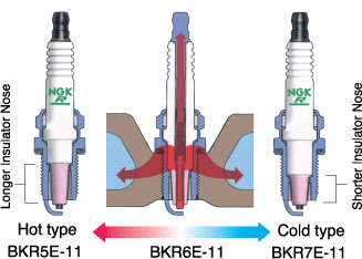
Heat rating and heat flow path of NGK Spark Plugs
chartheatratingflowpath-2.gif

The insulator nose length is the distance from the firing tip of the insulator to the point where insulator meets the metal shell. Since the insulator tip is the hottest part of the spark plug, the tip temperature is a primary factor in pre-ignition and fouling. Whether the spark plugs are fitted in a lawnmower, boat, or a race car, the spark plug tip temperature must remain between 500C-850°C. If the tip temperature is lower than 500°C, the insulator area surrounding the center electrode will not be hot enough to burn off carbon and combustion chamber deposits. These accumulated deposits can result in spark plug fouling leading to misfire. If the tip temperature is higher than 850°C the spark plug will overheat which may cause the ceramic around the center electrode to blister and the electrodes to melt. This may lead to pre-ignition/detonation and expensive engine damage. In identical spark plug types, the difference from one heat range to the next is the ability to remove approximately 70°C to 100°C from the combustion chamber. A projected style spark plug firing tip temperature is increased by 10°C to 20°C.


Tip Temperature and Firing End Appearance
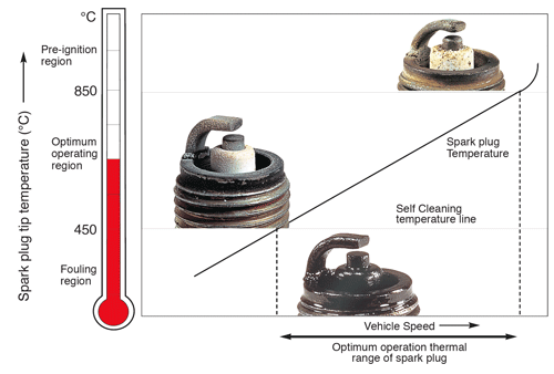
charttempfiringend.gif

The firing end appearance also depends on the spark plugs tip temperature. There are three basic diagnostic criteria for spark plugs: good, fouled and overheated. The borderline between the fouling and optimum operating regions (450° C ) is called the spark plug self-cleaning temperature. The temperature at this point is where the accumulated carbon and combustion deposits are burned off.

Keep in mind the insulator nose length is a determining factor in the heat range of a spark plug, the longer the insulator nose, the less heat is absorbed, and the further the heat must travel into the cylinder head water jackets. This means the plug has a higher internal temperature, and is said to be a hot plug. A hot spark plug maintains a higher internal operating temperature to burn off oil and carbon deposits, and has no relationship to spark quality or intensity.

Conversely, a cold spark plug has a shorter insulator nose and absorbs more combustion chamber heat. This heat travels a shorter distance, and allows the plug to operate at a lower internal temperature. A colder heat range is necessary when the engine is modified for performance, subjected to heavy loads, or is run at a high rpm for a significant period of time. Colder spark plugs remove heat quicker, reducing the chance of pre-ignition/detonation. Failure to use a cooler heat range in a modified application can lead to spark plug failure and severe engine damage.


Below is a list of external influences on a spark plug's operating temperature. The following symptoms or conditions may have an effect on the actual temperature of the spark plug. The spark plug cannot create these conditions, but it must be able to cope with the levels of heat...if not, the performance will suffer and engine damage can occur.

Air/Fuel Mixtures seriously affect engine performance and spark plug operating temperatures.

  • Rich air/fuel mixtures cause tip temperature to drop, causing fouling and poor driveability
  • Lean air/fuel mixtures cause plug tip and cylinder temperature to increase, resulting in pre-ignition, detonation, and possibly serious spark plug and engine damage
  • It is important to read spark plugs many times during the tuning process to achieve the optimum air/ fuel mixture

Higher Compression Ratios/Forced Induction will elevate spark plug tip and in-cylinder temperatures

  • Compression can be increased by performing any one of the following modifications:
     
    a) reducing combustion chamber volume (i.e.: domed pistons, smaller chamber heads, mill ing heads, etc.)
     
    b) adding forced induction (Nitrous, Turbocharging or Supercharging)
     
    c) camshaft change
  • As compression increases, a colder heat range plug, higher fuel octane, and careful attention to ignition timing and air/fuel ratios are necessary. Failure to select a colder spark plug can lead to spark plug/engine damage

Advancing Ignition Timing

  • Advancing ignition timing by 10° causes tip temperature to increase by approx. 70°-100° C

Engine Speed and Load

  • Increases in firing-end temperature are proportional to engine speed and load. When traveling at a consistent high rate of speed, or carrying/pushing very heavy loads, a colder heat range spark plug should be installed

Ambient Air Temperature

  • As air temperature falls, air density/air volume becomes greater, resulting in leaner air/fuel mixtures.
  • This creates higher cylinder pressures/temperatures and causes an increase in the spark plug's tip temperature. So, fuel delivery should be increased.
  • As temperature increases, air density decreases, as does intake volume, fuel delivery should be decreased

Humidity

  • As humidity increases, air intake volume decreases
  • Result is lower combustion pressures and temperatures, causing a decrease in the spark plug's temperature and a reduction in available power.
  • Air/fuel mixture should be leaner, depending upon ambient temperature.

Barometric Pressure/Altitude

  • Also affects the spark plug's tip temperature
  • The higher the altitude, the lower cylinder pressure becomes. As the cylinder temperature decreases, so does the plugs tip temperature
  • Many mechanics attempt to "chase" tuning by changing spark plug heat ranges
  • The real answer is to adjust air/fuel mixtures by rejetting in an effort to put more air back into the engine

Types of Abnormal Combustion

Pre-ignition

  • Defined as: ignition of the air/fuel mixture before the pre-set ignition timing mark
  • Caused by hot spots in the combustion chamber...can be caused
    (or amplified) by over advanced timing, too hot a spark plug, low octane fuel, lean air/fuel mixture, too high compression, or insufficient engine cooling
  • A change to a higher octane fuel, a colder plug, richer fuel mixture,
    or lower compression may be in order
  • You may also need to retard ignition timing, and check vehicle's cooling system
  • Pre-ignition usually leads to detonation; pre-ignition an detonation are two separate events

Detonation

  • The spark plug's worst enemy! (Besides fouling)
  • Can break insulators or break off ground electrodes
  • Pre-ignition most often leads to detonation
  • Plug tip temperatures can spike to over 3000°F during the combustion process (in a racing engine)
  • Most frequently caused by hot spots in the combustion chamber.
    Hot spots will allow the air/fuel mixture to pre-ignite. As the piston is being forced upward by mechanical action of the connecting rod, the pre-ignited explosion will try to force the piston downward. If the piston can't go up (because of the force of the premature explosion) and it can't go down (because of the upward mo-tion of the connecting rod), the piston will rattle from side to side. The resulting shock wave causes an audible pinging sound. This is detonation.
  • Most of the damage than an engine sustains when "detonating" is from excessive heat
  • The spark plug is damaged by both the elevated temperatures and the accompanying shock wave, or concussion

Misfires

  • A spark plug is said to have misfired when enough voltage has not been delivered to light off all fuel present in the combustion chamber at the proper moment of the power stroke (a few degrees before top dead center)
  • A spark plug can deliver a weak spark (or no spark at all) for a variety of reasons...defective coil, too much compression with incorrect
    plug gap, dry fouled or wet fouled spark plugs, insufficient ignition timing, etc.
  • Slight misfires can cause a loss of performance for obvious reasons (if fuel is not lit, no energy is be-ing created)
  • Severe misfires will cause poor fuel economy, poor driveability, and can lead to engine damage

Fouling

  • Will occur when spark plug tip temperature is insufficient to burn off carbon, fuel, oil or other deposits
  • Will cause spark to leach to metal shell...no spark across plug gap will cause a misfire
  • Wet-fouled spark plugs must be changed...spark plugs will not fire
  • Dry-fouled spark plugs can sometimes be cleaned by bringing engine up to operating temperature
  • Before changing fouled spark plugs, be sure to eliminate root
    cause of fouling


User Login

Mailbox

You are not logged in.

© 2017 Modelgasboats.com. All Rights Reserved.