Tech Article ...by Scott Schneider
A very informative step-by-step article on how to modify a Zenoah engine...
If you decide to try and modify your engine yourself following the examples shown here, please keep in mind that you are doing so at your own risk. Modelgasboats.com shall not be held accountable should you not obtain the results that you expected. The end results are totally dependant on the work performed on the engine by the person doing the modifications. If you are not comfortable experimenting at your own risk, consider purchasing an engine from a professional engine builder. Building a strong reliable engine is always the result of much trial and error, and the information posted here is simply to give you ideas.
A little bit of background information on Scott Schneider:
- Scott has been working with and tuning 2-stroke engines for 25 years
- has held the NAMBA 6 lap - 1 mile National Record in G-1 Hydro for 4 years in a row!
- races with self modified engines such as pictured in the following.
Because of on going requests for something more step by step,
I followed my porting tasks today by taking photos so you can see the sequence.
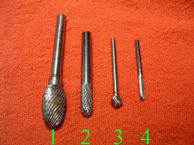
This first photo is of the tooling marked 1 thru 4..... And referenced at each photo to one used.
#1) a 1/2" elliptical on 1/4" shank
#2) a 1/4" ball end cylinder
#3) a 1/4" ball on 1/8" shank
#4) a 1/8" ball end cylinder
All being CARBIDE with chip breaker profiles.
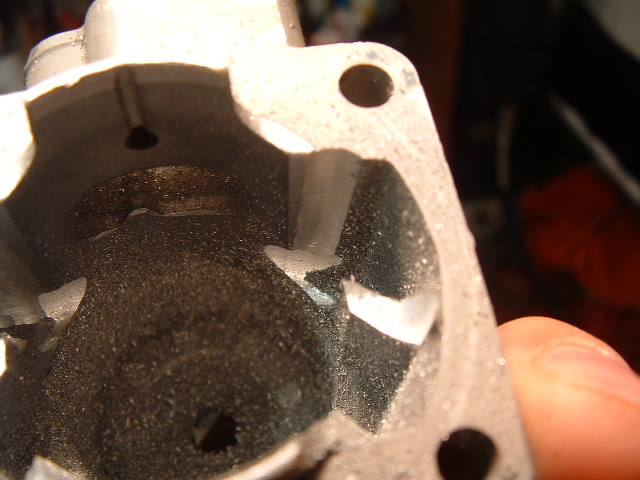
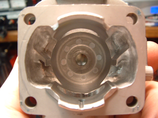
This shows 3 steps, 1st being the transfer bridge has been cut down @ 1/2" from cylinder base.(In a mill) 2nd the eyebrow cut made to transfer window facing intake port.(cutter #3) 3rd a vertical cut made to meet eyebrow so entire vertical edge of port can be opened up & blended into eyebrow area.(cutter #2)
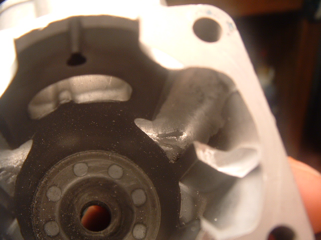
This photo the intake side transfer runner all cut and blended into eyebrow. (blended in with cutter #4)
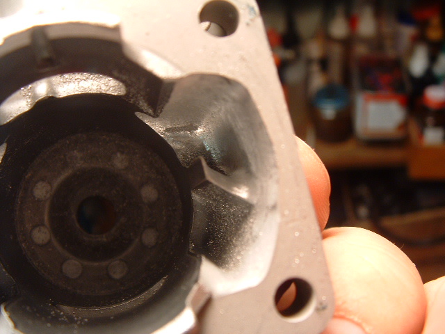
The shortened transfer passage bridge is sharpened. (cutter #4)
***** This next step DO WITH CAUTION !! ... If unsure you can be VERY steady & use the right cutter, Omit this step & leave Ex side transfer passages alone *****
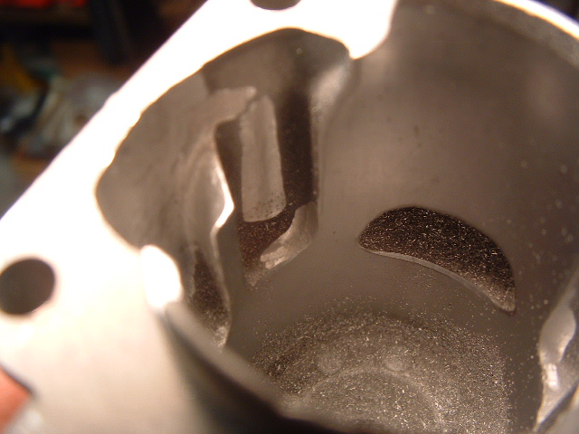
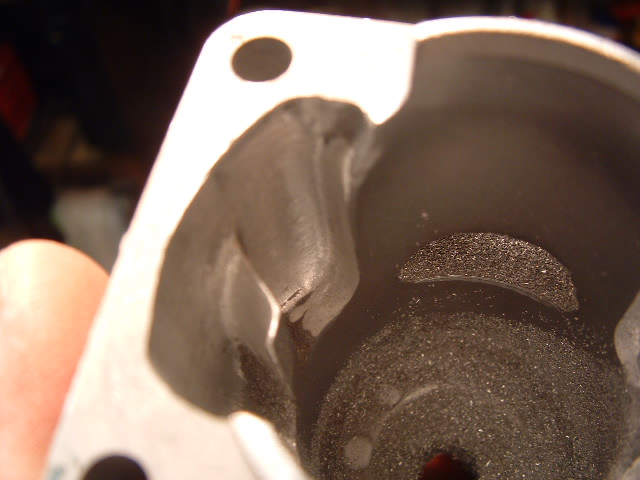
Now we have moved to the Exhaust side transfer passages & cut out the EX edge of upper transfer area to increase the width (This done with a 1/4 ball end cylinder (cutter #2) Keep cutter against outside area of transfer passage so the radius of the cutter makes an undercut edge that maintains the flow away from ex port. (See above *****)
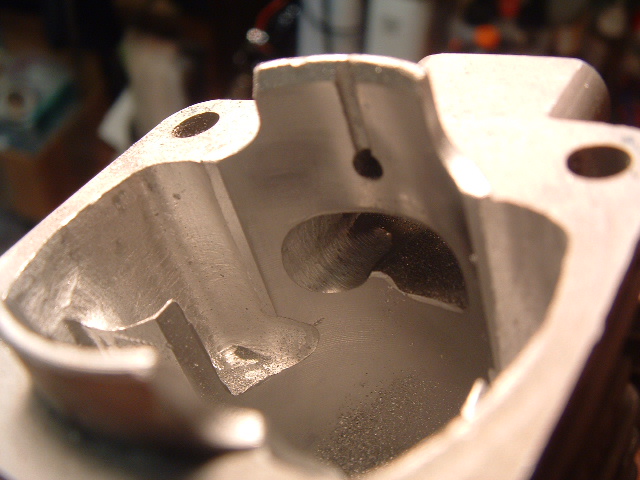
Now the intake window, raised slightly next to ring nub & widened to give @ 1/8" sealing edge width. (cutter #2)
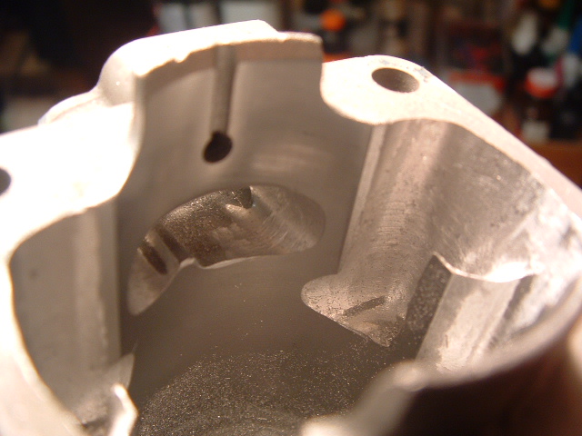
The other side of intake port, just widened. (cutter #2)
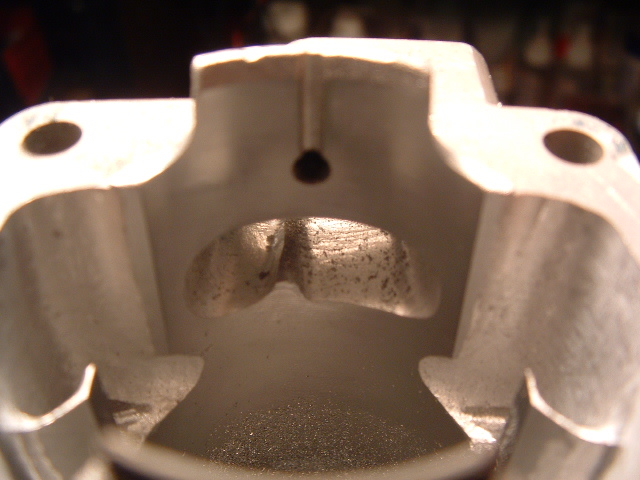
View once intake port was cleaned up and finished. (cutter #2 & #4)
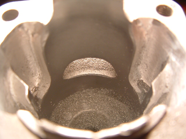
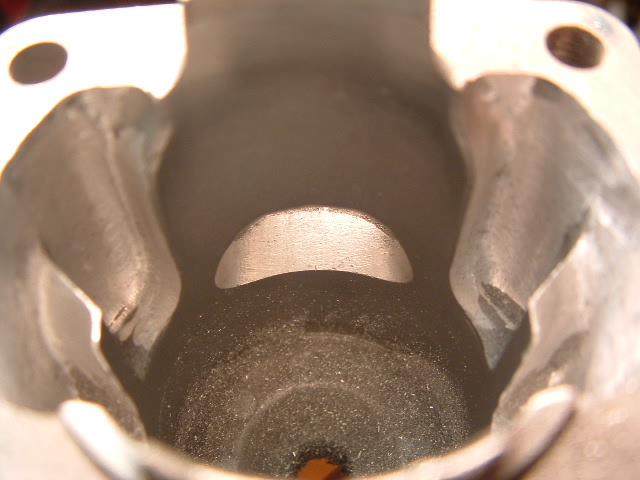
Stock exhaust port & once modified to @178 degrees. (cutter #2)
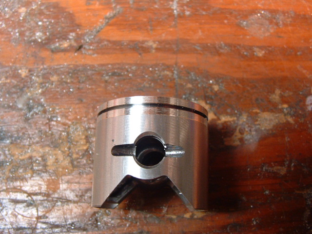
.002" cut made on top of piston (Total of .004" of diameter)
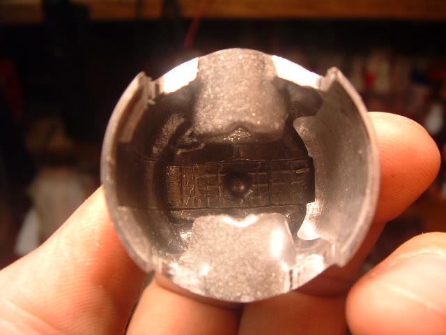
V shape cut out to increase area, also 1/2 of lightening process removing materal that would support a second ring. Other side not done yet. (cutter #2)
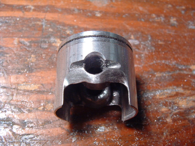
Area outside of pin boss area cut to force flow outward into transfer passages. (cutter #2)

The finished cylinder having had ALL the finishing blending work done & port edges chamfered. (cutters 2,3 & 4) Port chamfering done by hand with 220 then 600 wet dry paper.
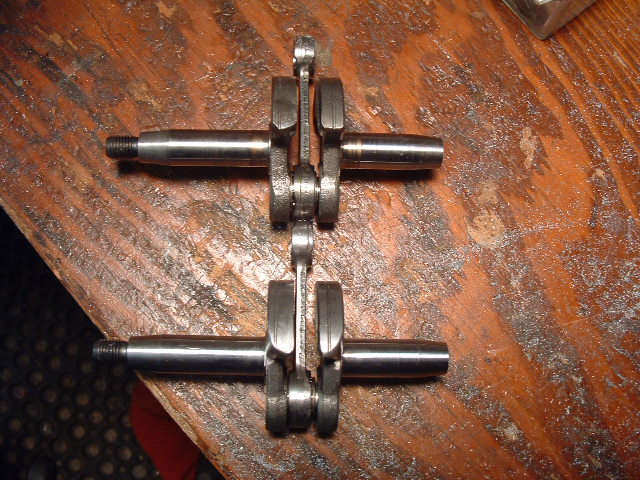
Crankshaft Turbo mod, shown with a stock one. (1" belt sander)
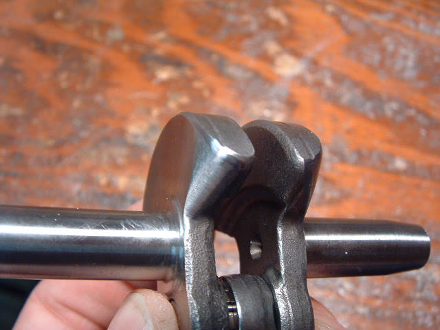
Close up of the finished turbo crank mod.
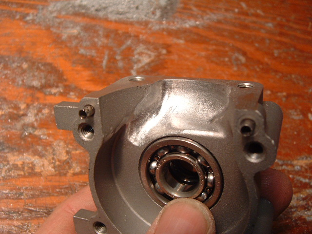
The crankcase done like this on both halves.(cutter #1)
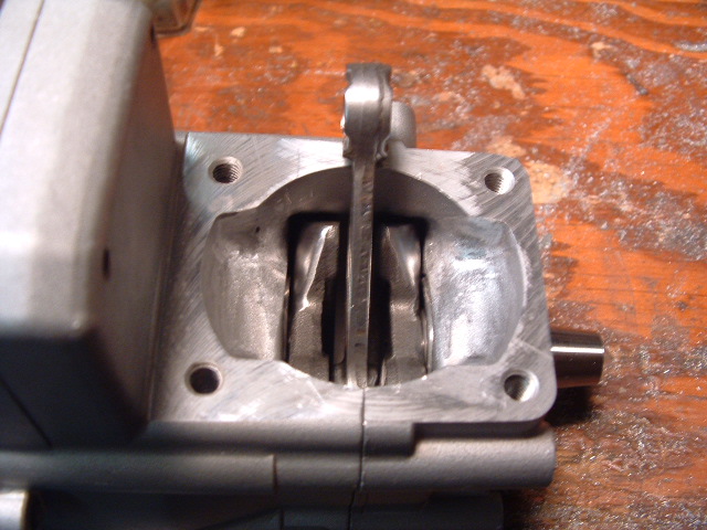
How cases look with crank installed. (view is crank position 90 degrees BBDC)
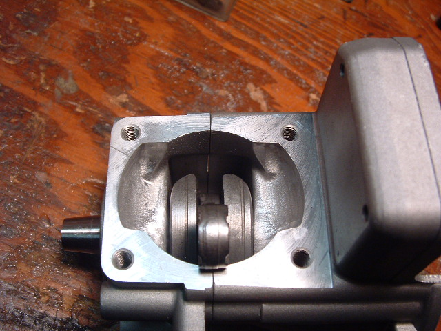
Crank position just BBDC (Note : factory ramps in cases left there & for GOOD reason) ramps direct charge up Ex side transfer edge.
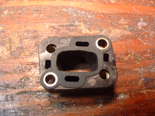
The intake manifold opened up to match cylinder & carburetor end opened up to .625" diameter. (cutter #2)
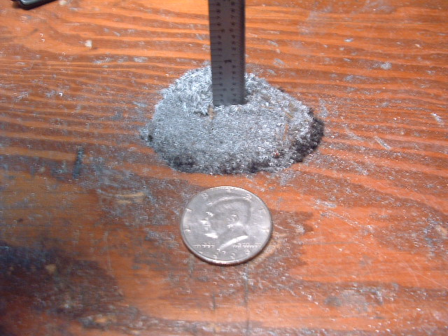
A pile of chips from this job that’s 1/4" deep and bigger than a silver dollar !! @ 2 1/2" around (50 cent shown)
That’s all folks .... Have fun!


