
Product Review Article...

A look at the Outerlimits XXX Racing Mono from Aeromarine Laminates...by Marc Levac.

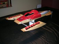
Featured in this article is the newest racing mono in the Aeromarine Laminates line-up of hulls, the XXX Outerlimits. Although this hull has a scale appearance, rest assured it is a very capable race hull!
The construction is typical of Aeromarine quality. The hull is light yet sturdy and features a high quality gelcoat finish. The keel and strakes are sharp and true. This hull is of the "shoebox" type, which means that the deck overlaps the bottom where the two are joined. The stringers and transom are made of ¼" marine grade plywood and are glassed into the hull from the factory. I've always loved Aeromarine hulls for their quality and appearance and this one does not disappoint. The detail to the deck and cowl are very impressive and make this boat a real eye catcher! It also makes the deck more rigid.
Overall length of the hull is approximately 45.5 inches and beam 12.5 inches. It is a deep "V" design.
I received the hull and hardware from Aeromarine about two weeks after having contacted Mr. Remy Haynes JR...this in spite of the fact that their area had been hit by severe storms and flooding. The hull arrived via airmail post and all was as promised.
When I first opened the box, the first thing that struck me was how sleek looking this hull was. I had seen pictures of the boat but for some reason it just looked better then and there!
Notice the certificate of authenticity that is supplied with the hull. This is something you receive with every Aeromarine Laminates hull. It includes a paper certificate with a serial number and a matching serial number imprint laminated in the hull itself! If you purchase a hull that is supposedly an Aeromarine hull, look for the certificate. If there isn't an Aeromarine imprint and serial number in the hull's bottom, be suspicious.


The package I received from Aeromarine was the hull and hardware combo. This kit includes just about everything you need to complete your build (less of course motor, pipe, and radio gear). Included in the box was the hull, radio box with lid, all linkage hardware, all transom hardware, antenna with mount, stuffing tube, flex cable, water outlets, bulkhead fittings, fuel tubing, water tubing, servo mounts, cowl locks and a gas tank with a fiberglass tray. They even included a propeller and prop nut in the kit!


The Build...
 After masking the transom, I drew some lines to identify the centerline (C.L.) of the hull and the centerline of
 the rudder (RCL). The strut was mounted directly on the hull centerline at ½" up from the keel. The prop blast water pickup is mounted to the strut bracket using the predrilled hole. The rudder was mounted on the RCL which is 2 ½" to the right of the hull CL. You can also see a horizontal line I drew from chine edge to chine edge. This is to make sure everything is square on the transom in reference to the hull bottom. Using this line as a reference, you can take a square and mark your CL and RCL lines. This is also your reference when mounting the hardware to ensure that it is square.


The Aeromarine rudder blade is a "wedge" type blade that is made of extruded aluminum. In order for this blade to properly perform its functions, you must follow the included instructions and sharpen the leading edge while removing the flat area (approx. first 1/8" of the blade leading edge). I went a little bit further with mine and actually filed it down to where the leading edge of the blade is right on the pivot axis of the rudder. This was done for two reasons: first I believe that rudders perform better when their leading edges aren't forward or aft of the pivot axis. Second, in order to get the trim tabs where I wanted them, this had to be done to prevent interference between the rudder and the inner right tab. (a rudder standoff could also be used).


The inner tabs were mounted at 1" from the keel; the outer tabs at 3-3/16" from the keel. Some trimming of the trim tabs' mounting surface had to be done to position them in the desired locations. The transom is pretty busy with all the hardware that has to be mounted, so this ended up being the optimal location for the trim tabs. The turn fin was mounted perpendicular (90 degrees) to the hull bottom and directly at the chine (intersection of the hull bottom and the freeboard).


After having done all the hardware mounting, I removed it all and removed the masking tape prior to re-installing everything to the transom.


Next came the radio box and engine install. The radio box supplied with the hull measures approximately 6" long x 5" wide x 1.75" deep. I must say getting all the radio components in this box was somewhat of a challenge, but it is doable! (I think the reason for supplying the kit with such a shallow radio box is to allow for sufficient clearance of the tuned pipe without having to cut up the hatch). I used the supplied servo mounts for the ¼ scale steering servo and standard size throttle servo. To save space I installed a small PCM receiver and a 5 cell (2/3 AA) flat battery pack that puts out 1100 mAh at 6.0 volts. I also made a servo "Y" harness to take advantage of the 6.0 volt battery. The radio box came with a pre-cut and trimmed transparent blue cover that I unfortunately broke while drilling it. I made a new replacement cover using clear 1/8" thick Lexan material. The supplied antenna was mounted in the radio box cover (personal preference). I use an O-ring on the mount to seal against the cover. The servos were mounted to allow straight line linkages to the carburetor and rudder. To mount the box in the hull I glued a piece of 1/8" plywood to the bottom of the hull and sealed it. This plywood is 5 inches wide and about 8 inches long so that it extends about 1 inch at the front and back of the box yet fits snugly between the 5 inch stringers. Pieces of angle aluminum hold the box in place from the outside without any holes drilled in the box.


The hardware kit did not include motor mounts (available separately from Aeromarine), so I used a set of Insane/CC Racing mounts that I had on hand. At this point I laid everything in the hull to check the center of gravity (CG) and found the optimal position for the motor. I wanted the CG at 31-33%. I then cut an opening in the starboard stringer so that it would not interfere with the carburetor and allow me to mount the engine as low as possible in the hull. The motor mounts used include a coil relocating bracket that allows the grey coil to be moved from its stock position to above the pull starter. This also helps to get the engine lower in the hull. I used a piece of 1/16" plywood as a shim under the motor when marking the stringers for the mount isolators.
The tank tray was mounted ahead of the motor using 3M 5200 adhesive.


To hold the stuffing tube in the hull I ordered a "T-bar" from Butch Fields. You can read more about the T-bar here.


Nearing the end...
It was now time to mount the cowl. I usually completely cut off the back half of the cowl on monos to allow for plenty of space and access for the tuned pipe but I just could not bring myself to cut up the beautiful cowl. I just loved the scale appearance too much and had to preserve it. I started by opening up the obvious...the air scoops on the back section. These would definitely push a lot of fresh air into the cowl, but it did nothing to get the hot air out so I had to do more. I wanted fresh air to come in from further up front into the boat. To do this I installed a small duct in the port side of the front deck. I glued it in with 3M 5200 adhesive. This should help direct a bit of cool air to the tuned pipe. To further cool the pipe I opened up the rear port side window in the cowl. To allow all the warmed air to exit the hull I installed an air screen on the back of the cowl. I also added a small reverse air scoop in the side of the hull next to the tuned pipe to help suck out some of the hot air.


The water lines were routed through the hull using the supplied through transom fittings. Water and gas lines were secured in the hull using the new "Handy Hooks" from Aeromarine. These are made of aluminum and come with stainless steel mounting screws. They are available in small and large size and also in straight and 90 degree configurations.


The tuned pipe bracket I used was one I made myself (the hardware kit also includes one so you don't have to make your own).
The cowl is mounted using pins in the front and Aeromarine cowl locks in the back. The front pins were made using stainless steel screws glued in place with epoxy and lined with silicone tubing.


On Water Results:
I charged the transmitter and receiver batteries and headed out to the lake to try out the boat. On the first try the boat was extremely wet and darted hard to the right. I had to take it back in and raise the trim tabs a bit. On the second run the boat was better yet still a little bit too tight. The water was very flat with no chop at all and the hull was very sticky. I had to raise the strut a little bit to get the boat to loosen up more. With some good chop it probably would have been ok as is though. I ran the boat some more and it was now a little bit too loose but was extremely fast and surprisingly handled the power of the J&G/Zenoah kit engine. After about ½ hour of fun running, I decided I would take it back to the shop and do a few slight modifications.
Back at the shop:
At the lake I had noticed that the boat was extremely sensitive to steering input which made it very difficult to turn in a normal radius and most often I turned too tightly and forced the engine off the pipe. The boat also suffered from considerable prop walk. To correct this I made a rudder extension that positioned the rudder leading edge about even with the propeller's trailing edge. The extension was made with a piece of 3/16" thick aluminum plate. The extension fits in the stock transom brackets and butts against the transom. At the rudder end I drilled 2 holes, one for the stock rudder bolt and a second for a small 4-40 "shear" bolt so that the rudder can kick back in case of impact.
 The second modification I made was to the rudder blade itself. The stock rudder blade has a single water pickup hole on the right (starboard) side. This is perfect for ensuring water flow even during right turns, but I noticed it was starving the engine of cooling water when I had to input a bit of left rudder to keep the boat straight (during the tuning
 process). The left rudder input should not be required usually, but I wanted all bases covered so I put the blade in my mini mill and made a second water intake hole on the left (port) side of the blade about ½" above the stock one. Both pickup holes lead to the same water passage in the blade. This will ensure positive water flow regardless of rudder position. (Please note that this is not a required modification...the stock pickup will supply adequate water flow unless using too much left rudder input to correct for prop walk, which is a bad thing in any case.)
Here is some video taken at the lake on the first time out. This was before I installed the rudder extension.
Here is a SHORT VIDEO CLIP of the same boat with the rudder extension installed.
This time running a full mod Zenoah 260, same pipe.
At the Lake Again:
The rudder extension improved the boat's handling considerably. I ran the boat for several laps and was quite satisfied with the way it handled. The dual inlets in the rudder also improved water flow through the engine (the prop-blast pickup feeds the tuned pipe). I still have to try more props and settings on this hull to find the optimum setup with the J&G kit engine, but it is clearly a very capable hull worthy of winning races!
What I liked about the XXX Outerlimits kit:
- Great scale looking hull
- Beautiful gelcoat finish
- Inside finish very clean
- The hatch fit the deck perfectly
- Full hardware kit (only thing not included in kit are motor mounts...available separately)
- Great performing boat
- Great price/quality value
What I thought was missing:
- Setup instructions (in the works)
- Rudder extension (for optimum handling)
- T-bar (personal preference)
Final words...
I really enjoyed building and running the XXX Outerlimits boat. As with most Aeromarine hulls, I love the fact that it has a scale look, and matched with great performance this makes the XXX a winner in my book!
If you are in the market for a new mono and want to go fast and look great, give the XXX Outerlimits a shot!
Happy Boating!
Price of the kit tested: $525.00 USD Retail. A very competitive price considering all that is included in the hardware package!
Price of Hull Only: $299.00 USD Retail.
* prices subject to change. Check website or call to confirm pricing
To Order: www.aeromarinerc.com or call: 302-628-3944
Listing of parts used for this review:
Hull: Aeromarine Laminates XXX Outerlimits Fiberglass Hull
Hardware: Aeromarine Laminates XXX Hardware Kit
Motor: Zenoah G260PUM with J&G Hemi V2 Kit
Motor Mounts: Insane/CCRacing mounts
T-Bar: BBM T-bar
Tuned Pipe: Needforspeed Hobbies prototype 0 band steel pipe
Muffler: T-Mod Carbon Fiber Stinger Muffler
")
