Product Review Article ...
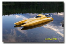
A look at the Generation 1 Insane Cat...by Marc Levac.

After shopping around for a new catamaran hull for a while, I finally decided to go with the new Cat hull from Insane Boats. After contacting Jeff Michaud, designer/builder of the hull, I knew I wanted one. His responses were always prompt 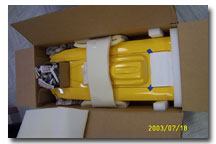 and informative. I wanted a hull fast so I asked if he had one ready to ship, and as luck would have it, he had
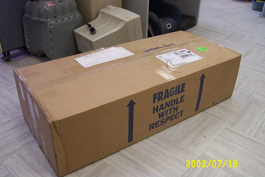 a yellow one ready…my favourite color! I got a money order to Jeff by courier (2 days) and within one week the big brown box arrived, from California USA to Québec Canada! The hull was very well packaged inside a sturdy, well identified cardboard box.
I inspected the hull thoroughly and must say that the glass work is among the best I've seen so far. The gelcoat is about as flawless as they come, with a nice gloss. The steps and all lines of the hull are straight and sharp. The hatches fit perfectly in place. The attention to detail is excellent. The hull also is considerably lightweight and surprisingly stiff.
Included in the box was a set of Insane decals, and setup instruction sheets. Two different setup sheets were supplied to me by Jeff. One is Jeff's recommended setup with J&G hardware, and the other is setup info from Mike Hoffmeister with Speedmaster/Octura hardware. I opted for the latter for the simple reason that I happened to have all the necessary hardware on hand. I'm sure either setup performs well, as these two individuals are very respected racers who obviously know how to setup a hull for peak performance.
Setup:
A few things need to be mentioned before going any further. Due to some optical illusions, some lines on the transom and parts in pictures may look as though they are crooked, but they ARE NOT! Attention to detail and precision is a must in assembling performance R/C boats. Also, the sequence and methods taken in the following steps are only GUIDELINES reflecting my personal preferences.
Ok, so on with the setup of the hull. Once you are ready to start and have a good idea of where everything is going to go, tape up the back of the transom with some masking tape. By doing this, you 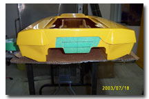 can mark some reference lines on the transom with a fine point marker. The tape will also help prevent chipping the gelcoat when drilling. Mark the hull centerline and a few horizontal reference lines. It is very important to note that this must be done with the hull on a very flat working surface and using a straight edge. Now assemble the strut and set it to a neutral setting. This will allow for ample up
 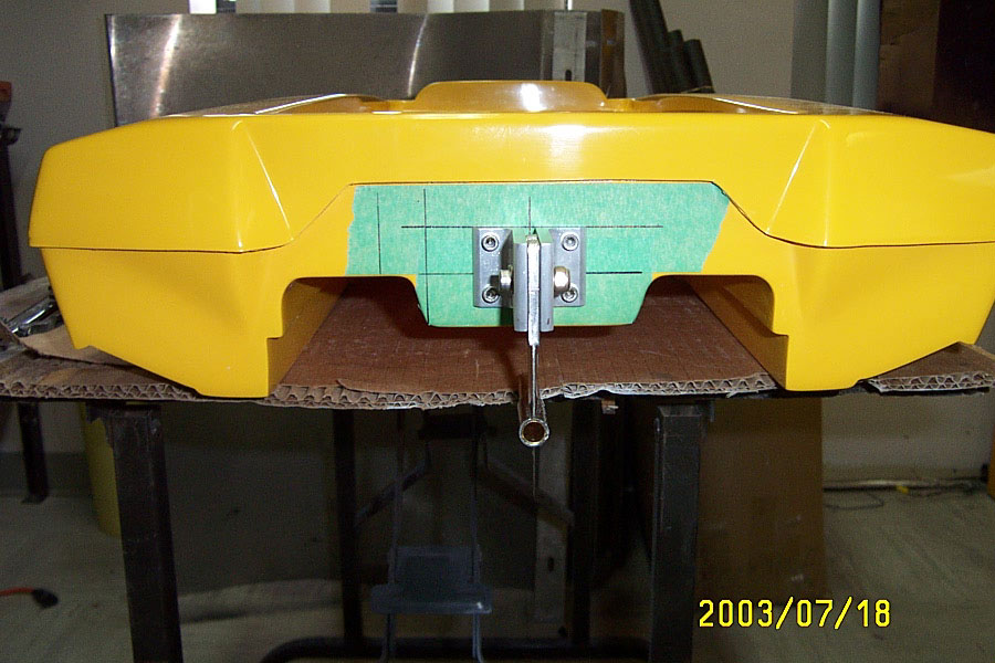 and down adjustment of the strut once installed. Position the strut on the transom, with the bottom of its housing flush to the bottom of the sponsons and mark one of its mounting holes on the transom using a fine tip marker. Use the hull centerline mark and horizontal marks as guidelines to position the strut properly. Drill the hole in the transom and mount the strut with the supplied hardware. I like to drill exact size hole so the bolt will fit tightly in the hole in transom. Once mounted to the transom, double check the alignment of the strut and tighten the bolt holding the strut to transom. Drill the mounting hole for the opposite corner of the strut bracket. Install the second bolt and secure it in place. You can now drill the two remaining holes and secure all bolts and nuts. The strut is done.
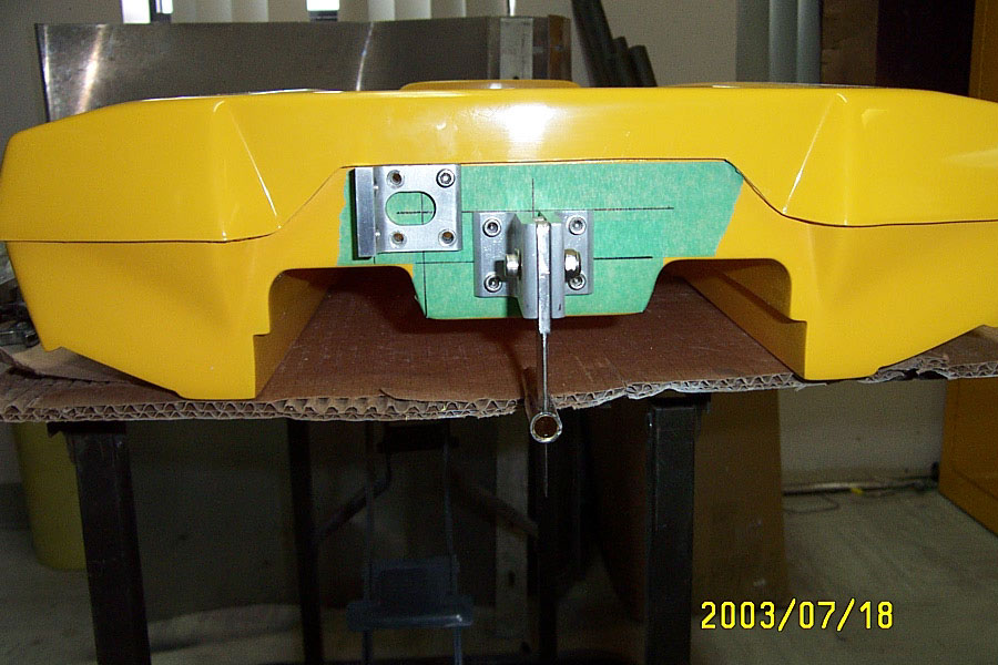 The mounting of the rudder is accomplished by following the same basic steps as for the strut. For this project I was using the Speedmaster 60/90 single pickup rudder blade on a 3.75 inch extended bracket. I have my rudder set at 2.5 inches to the left of hull centerline and with the blade at 3 inches below sponson pads. I removed the blade and extension and mounted the bracket only, this way you have better access to marking and drilling the holes.
  After installing the bracket, mark the big opening for the rudder pushrod. A rotary tool and mini milling bit work great for drilling out this hole. You can also use a drill and large drill bit, but be very careful not to damage the gelcoat. Once everything has been drilled and fitted, remove all hardware and the masking tape.
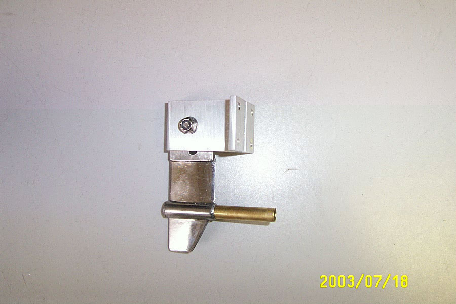 The strut I used for this setup is the Octura short stainless steel strut blade with skeg, mounted to a set of standard Speedmaster strut brackets. I did however modify the strut somewhat since I prefer collet setups with welded cables. I removed the Teflon bushings from the strut housing and inserted a length of 11/32" K&S brass tubing in the strut. The stuffing tube (5/16") will fit snugly into this tubing, and will then be fitted with a Rocket City Racing strut bearing as on all my collet drive setups.
 After removing the tape, remount the strut and complete rudder assembly to the transom. I used a bellows type pushrod seal for the rudder pushrod hole in the transom. I also used a custom made aluminum bracket which holds my ¼ scale rudder servo inside the hull. This bracket is threaded to accept the 8-32 rudder mounting bolts. With this setup, the servo and rudder are aligned perfectly fo
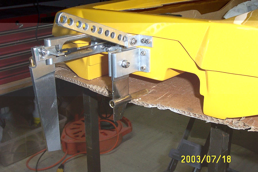 r a straight line push/pull of the rudder. Thanks to my boating partner Michel J. (rc_michel) for this neat trick! I also made a custom tuned pipe mount bracket using angle aluminum. This was fixed to the boat same as the rudder and strut.
Now is a good time to set everything in the hull at their appropriate location and check for desired CG (Center of Gravity). Engine placement for my setup came to 13" from center of sparkplug to back of transom. * Note: I setup the boat with exposed servos, so weight distribution is a little different than with a typical radio box installation.
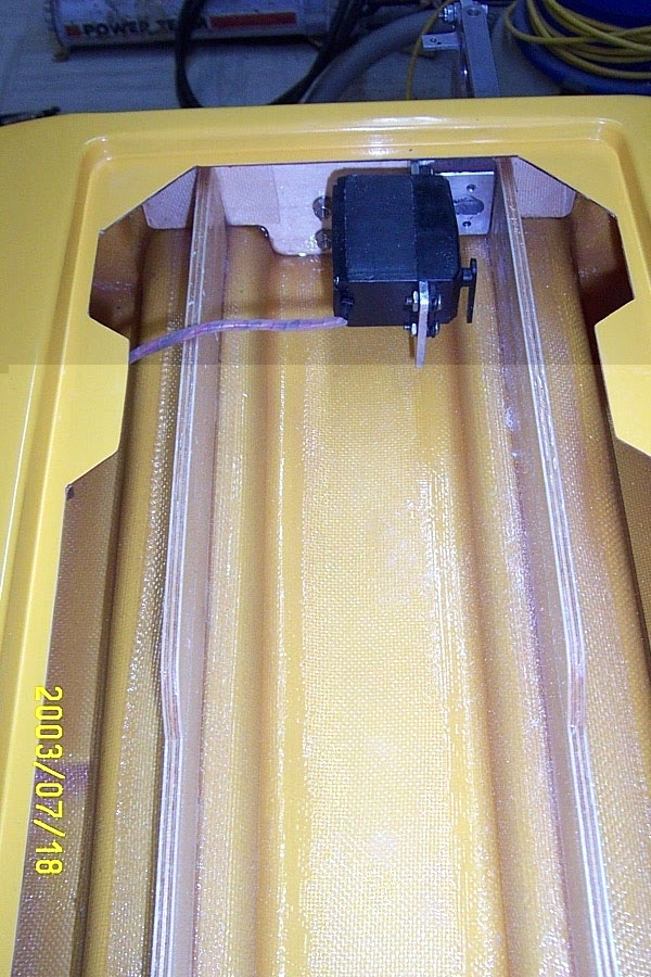 Now is a good time to install your pool noodles for floatation. Once the motor is installed it's almost impossible to get noodles in the sponsons. It is a very tight fit even without anything installed in the hull.
Mounting the engine is the same as with any hull. Install the complete mounts with brackets on the engine. Drop the engine between the stringers, position as desired and mark the holes for the brackets. I recommend marking the back (collet end) mounting holes first. Drill the holes, and secure the back mounts with the necessary hardware. Once this is done set the angle of your engine and mark the front (pullstart end) mounts. Drill the holes and secure the front mounts. I gave mine very little angle to try and minimize the bend in the stuffing tube. It worked out well.
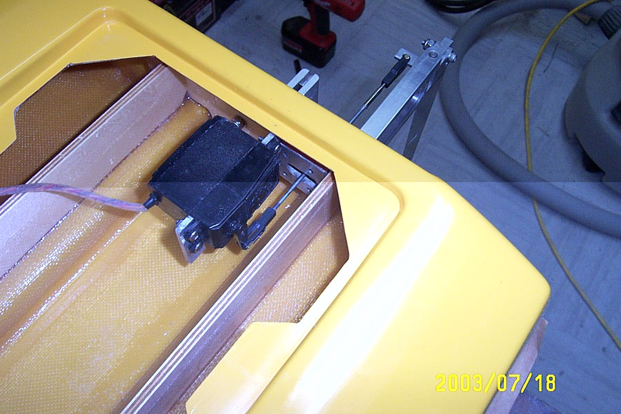
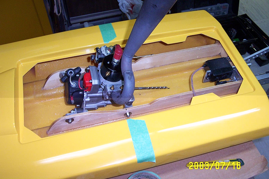
Now comes one of the hardest parts: cutting out the hole in the bottom of the tunnel for the stuffing tube. A good trick is to install a collet on your engine and fit a ¼" shaft ( a drill bit works great) into the collet. This helps a lot with the alignment. I used a rotary tool with mini milling bit to do the cut-out. Go VERY slowly checking often. The goal here is to make the hole only big enough for the stuffing tube liner (11/32" brass tubing) to fit through. Since this tube is on an angle, the hole will be of oval shape. Line up where the tube will exit the hull with the drill bit that is fitted to engine. Make a 11/32" opening and start opening it up lengthwise towards the transom. Fit a piece of 11/32" tubing in the hole and see if you can line it up with the drill bit. Keep fine tuning the opening until you can get the tubing through and slip it over the drill bit without forcing it. If you are careful and patient doing this, you will have just the right size opening and not have a tough fiberglassing job ahead of you.
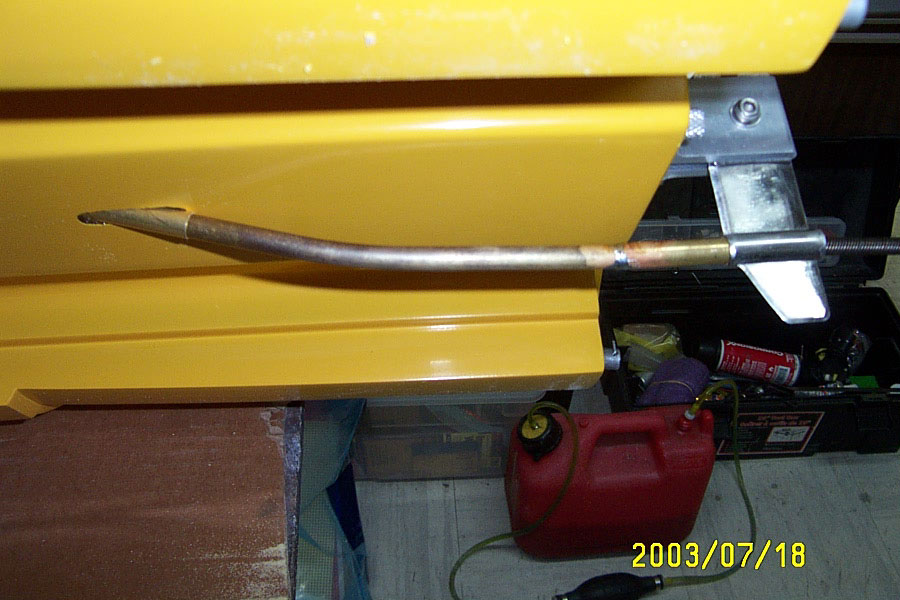
The next step is to laminate the stuffing tube liner to the hull. Cut a piece of brass tubing of the correct length (I measure about 2" from the collet and just long enough to exit the hull bottom). After cutting this piece, ream the inside on both ends and make sure your 5/16" stuffing tube slides through it. It's much easier to do that now than after you've laminated it to the hull. Some people will make a wooden wedge form block to support the tube in the hull. That is fine. I decided to try a different method and wetted and rolled fibreglass matt to support the underside of the tube. Before you start this step, make sure the area to be laminated is very clean. Clean the inside of the hull with acetone. Also coarse sand the outside of the brass tube and clean it with acetone. Mix a small batch of resin and have
 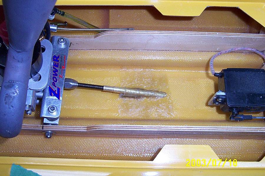 some 1" x 5" matt strips ready. There are many ways of doing this, but here is how I did it. I slipped the tube in place over the drill bit that was still in the collet, and taped it there. Then I temporarily installed the 5/16" brass stuffing tube to get every thing lined up with the engine and the strut. I then masked the underside of the hull where the tube exits. I did this very carefully, as I wanted a nice clean finish on the underside and did not want to have to do any work on that side. Taping it very carefully prevents any resin from leaking through from the inside. I wetted some matt and rolled it and stuffed it under the tub in the hull (in place of a wooden wedge). I did a small roll and a larger one t
 o fit the shape nice and tight. Then I wetted the strips of matt I had previously cut out, and sponged them to remove all excess resin. The strips were then layed over the tube, perpendicular to it working all the air out from underneath. You must keep a close eye on this until it sets as air bubbles tend to form. It is desirable to have no air bubbles at all, as they will weaken the bond to the tube and hull. If the preparation was well done, and no excess resin was used, you will have a nice clean finish, and a secure bond.
 An alternative method to installing stuffing tube is to use the Stuffing Block Mount from Butch Fields.
At this point you should be ready to install most other accessories in the hull. For most setups it will be time to setup the radio box with servos and linkages. The rudder servo on my setup was installed earlier at the same time as the rudder. I then installed the throttle servo using the PCMBOATS Direct Throttle and a pvc servo mounting bracket fixed to the stringer. I use foam tape around the servo to isolate against vibration. Next I installed the 1000ml I.V. Bag fuel cell (in the photos you see a 500ml bag, but I changed it to a 1000ml). For more info on I.V. Bag setups click here. I fitted the fuel system with a Dubro large scale quick fueler. The fueler is fixed to the stringer with an aluminum angle bracket. It is held in place with one of the engine mount bolts. The radio box used in my boat is for the receiver and batteries only. I like to use Lock & Lock brand containers available from Wal-mart stores for only a few dollars. These containers have a great lid with rubber gasket all around. This is really a matter of preference though. To hold the radio box in place in the hull I like to use a few strips of industrial strength Velcro. I epoxy the hook strips in the bottom of the hull, and the loop strips to the radio box. I installed the antenna as close as possible to the radio box, on the starboard side of the hull.
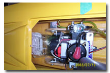 I also, always install a failsafe device in my boats. I use a very simple method of mounting my Shark Racing Failsafes. I simply cut out a space in a piece of pool noodle so the failsafe will fit inside it tightly and use a dab of Goop to hold it in. The noodle is then fixed at the desired position in the hull. You can see it in the pic below (piece of pink noodle). Of course it could be mounted just like a servo also. Again, this is a matter of personal preference. I prefer not to have the failsafe in the radio box.
You can now complete all connections for radio equipment and test for proper operation. Install all water 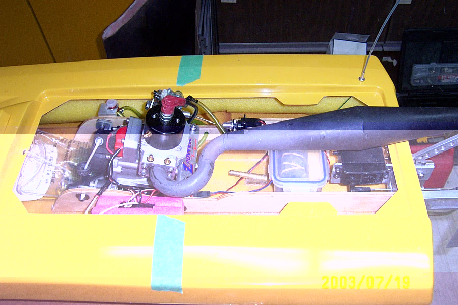 lines and water outlets, inlets. I used a single cooling circuit with one thru-transom inlet and one water outlet on the top of the port side sponson. This way I can always see water spraying out when the boat is running as the water sprays up and out.
To mount the hatch, I had first gone with the Velcro method for the back of the hatch and brass pins for the front. This method has worked fine for me in the past. I have since switched to cowl locks for the back, as the Velcro just didn't seem to hold the hatch firmly enough on this hull. There is also a small hatch cover that fits between the transom and main hatch. This one holds easily in place with Velcro. Decide which fixing method you wish to use for the hatches, and cut the opening in the back of the main hatch for the tuned pipe to exit. It is also good to open the scoop on the exhaust side and the one over the sparkplug for adequate cooling under the hatch.
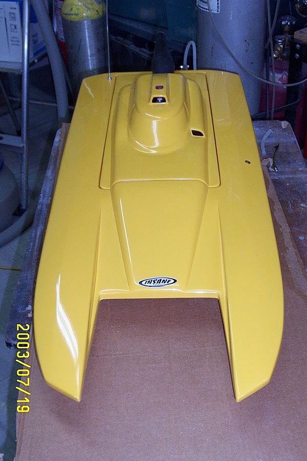 All that's left now is to install your flexshaft, drive dog, and favourite prop. Make all necessary adjustments to throttle and rudder servos . For the rudder, only about 10-15 degrees of throw is required as baseline setting.
On the water:
-
- Motor: Zenoah G260PUM (modified)
- Pipe: new Blois wrap to center steel pipe
- Prop: Proshop 7016/2 (modified)
The first thing I notice when I first hit the water with my new Insane Cat was how light it felt. Acceleration was instantaneous and very impressive. Jeff suggests that adding weight in the hull (on center of gravity) may be necessary in race or rough water conditions. I am still experimenting with this, but so far have about half a pound on C.G. Without any weight it is amazingly fast, but might blow over.
Of course my setup wasn't perfect, but it was close and ran very well for a first run. I was running a 6717/3 prop for the maiden voyage. I soon after switched to a 7016/2 as recommended by Jeff, and the performance increased very much. The hull cornered very well, without digging in the turns and with very little loss of speed. Speeds in the 60's will not be uncommon with this hull.
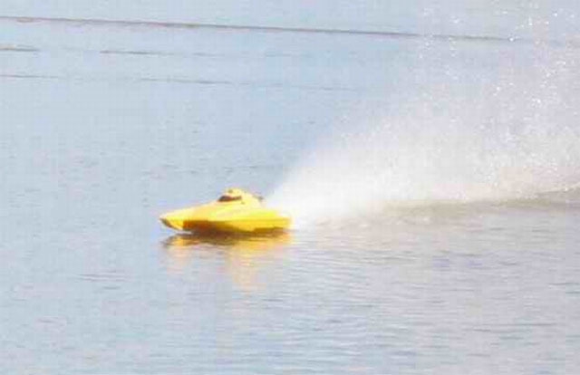
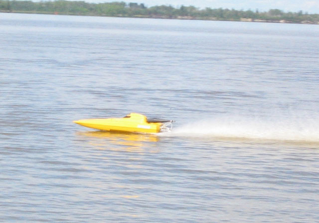


Checkout a video of the this cat
Comments:
- great performance
- very nice finish (quality fibreglass work)
- excellent customer service
- unique design and appearance
- limited access to sponson area (for getting flotation in)
- can be less forgiving than some other cat hulls (probably not the best hull for beginners)
Properly setup, with the right engine, pipe, hardware combination, this is a very impressive boat. It also has a refreshingly new look, that stands out from the catamaran class.
So, if you're in the market for a new Cat hull that's both performance oriented and an eye pleaser, look no further!
Happy boating!
Contact Information:
INSANE BOATS
Website: www.insaneboats.com

