In this article we show you how to measure port timing and squish on a Zenoah style engine...
I have been asked several times about how to accurately check and measure port timing and squish clearance on Zenoah style engines...well here it is in a nutshell. It really isn't that difficult to do if you have access to the required tools.
Let's start with measuring the squish area.
 What is commonly referred to as "squish clearance" is the actual clearance between the highest part of the, piston when it is at Top Dead Center (TDC) and the lowest part of the cylinder dome, which is the actual "squish band". There are several methods to measure this.
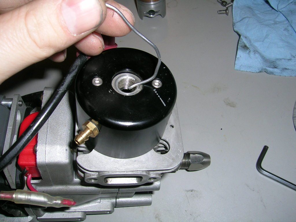
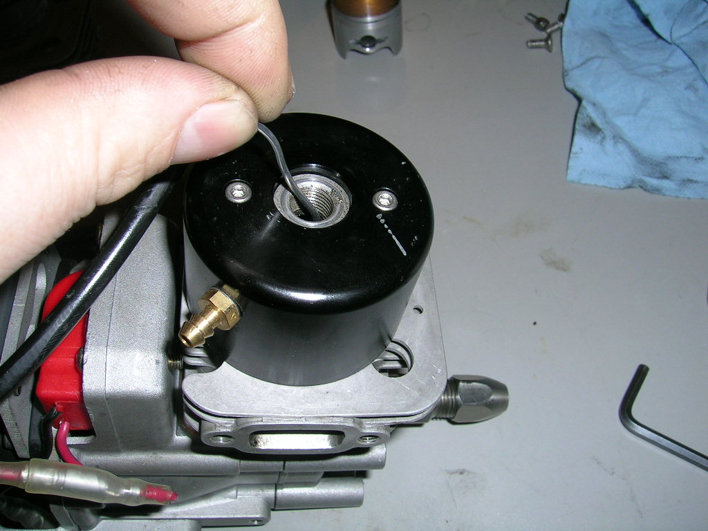
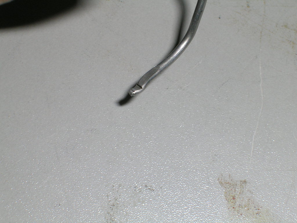
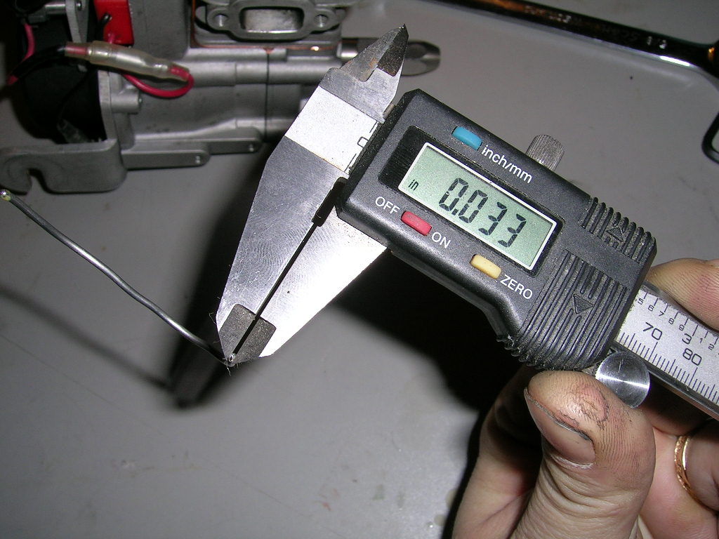
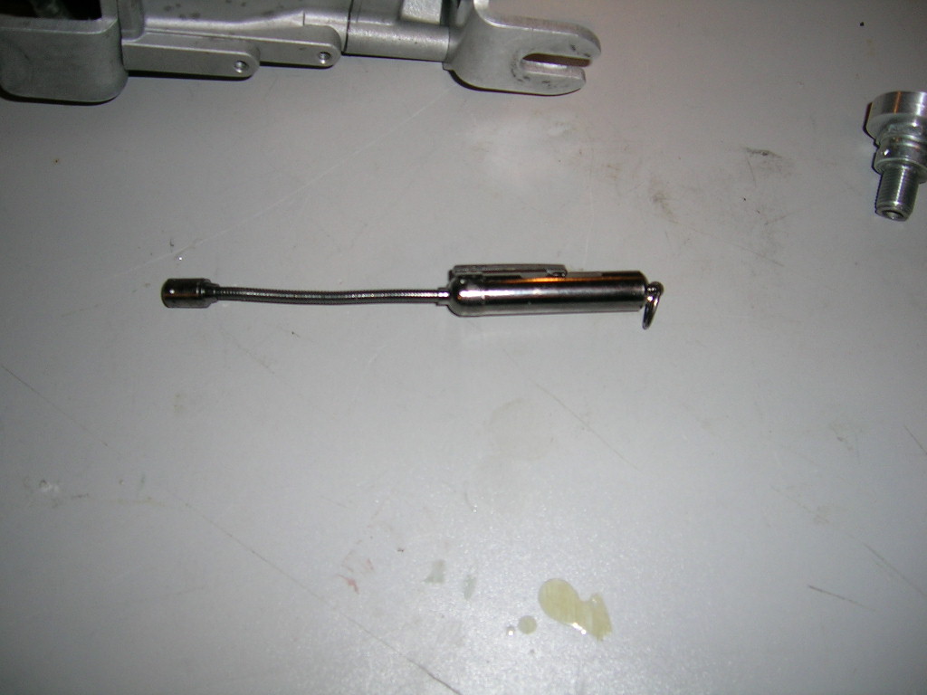
Probably the simplest method (and possibly the less accurate in my experience) is the "soft solder" method. This consists of taking a piece of soft solder and bending it so that it can be inserted into the cylinder via the spark plug hole. You position the solder so that it will get squished between the piston and the squish band as you turn the crankshaft over by hand. You then use a calliper to measure the thickness of the solder where it was compressed by the piston. This is very quick and easy and will give a "good idea" of the squish clearance without the need to take the engine apart. Care should be taken to position the solder inline with the crankshaft to get the most accurate reading possible. If the solder is to either side of the crankshaft axis, the piston can "rock" in the bore and falsify the reading.
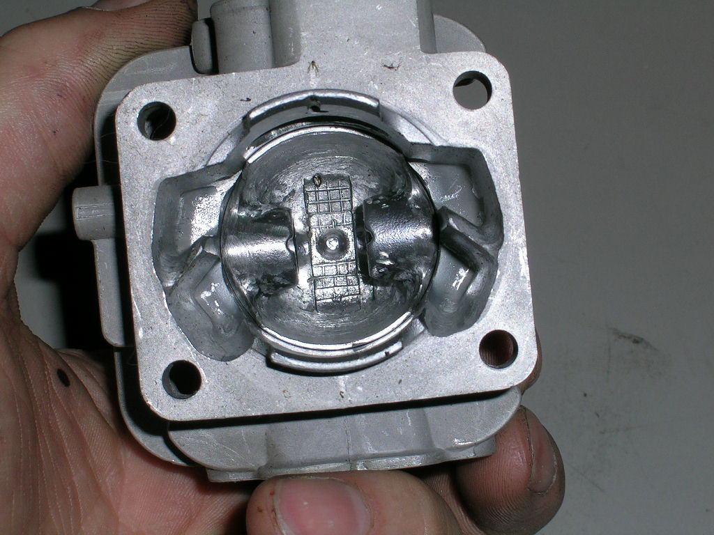 The following two methods are quite similar but use different tools for measuring. For these methods you have to first remove the cylinder and piston from the engine. You then insert the piston into the cylinder (you can remove the ring to make this easier) and position it as it would be in the engine. In other words, the ring retention pin towards the intake port and the arrow on the top of the piston (if it's still present) towards the exhaust port. Make sure the piston is tight against the top of the cylinder.
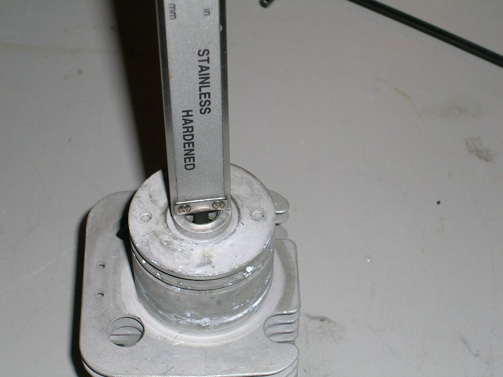 This first of the two methods is to take a depth measurement with a calliper through the spark plug hole. Double check and make sure you do this accurately. Take note of this measurement.
Then you re-install the piston and re-assemble the cylinder to the engine. Now you take your calliper again and moving the piston to TDC find the highest point that it travels to and note this measurement. The difference between this measurement and the previous one will give you the squish clearance.
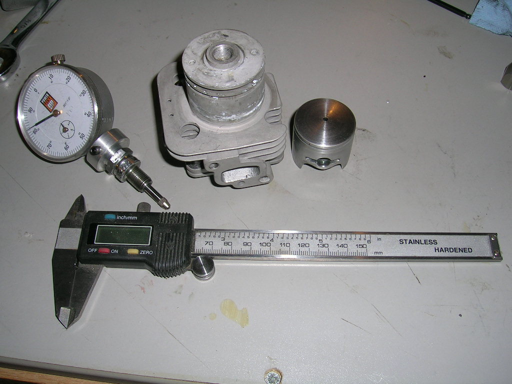
The second method uses basically the same procedure just mentioned, but uses a dial indicator to take the measurements. To do this you will need a fixture for your dial indicator. I make my own using an old spark plug and machine an adaptor that is
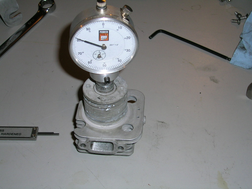 pressed into the old spark plug base and secures the dial in it. This is fairly easy to make if you have access to a lathe. I really like this method. You do as with the caliper, except that once you put the dial indicator on the cylinder you leave it on until you are done taking both measurements.
In other words, install the dial in the cylinder you have removed from the engine and make sure it's tight. Push the piston up into the cylinder and take a reading off the dial. Take note of the reading. To make things even simpler, you can zero the dial at this point. Then, leaving the dial installed on the cylinder, re-assemble the engine and rotate the crank shaft to get the piston to TDC. This will be the highest reading you can get on the dial. The difference between this reading and the previous one is your squish clearance.
Measuring Port Timing
Measuring intake and exhaust port timing is no more difficult than checking squish clearance, in fact it's probably easier since there is no need to disassemble the engine. You will however need one very important tool...a degree wheel. You've probably heard this term before, maybe you've used one, and maybe you haven't but fear not, it isn't black magic!
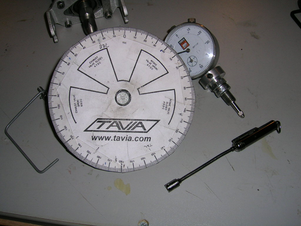
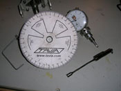
You can purchase commercially available degree wheels or you can do like me and make your own quite simply. If I were doing engines professionally I might be using fancier tools, but since this is a hobby for me, what I can make myself and get good results with suits me just fine. My degree wheel is simply a printout of the one found at www.tavia.com . I cut the printout and glued it to a piece of cardboard that I mounted to a 1/4" bolt. The bolt fits right into and engine collet so it's easy to mount the wheel to the engine. I made the pointer from a piece of stiff steel wire and mount it to the engine with a bolt in one of the back engine mount holes. The wire I used to make the pointer is a little thick so when taking measurements on the wheel I pick on edge to take the readings from and stick to that one for the entire process.
Let’s start by checking the exhaust port timing. Again, there are different ways of doing this, and of course some will argue that their methods are better but if you do as explained here and do it carefully, you will get accurate readings. I don't bother with zeroing the wheel or anything like that. There is no need to make things more complicated than they really are!
* if you do however prefer zeroing the wheel, you can do it using a dial indicator setup like the one used for checking the squish, or you can use a piston stop. With the dial, simply bring the piston to TDC and zero the wheel. With the piston stop, you install the stop and rotate the crank one way until the piston hits the stop. Zero the wheel at this point and then rotate the crank the other way until the piston hits the stop again. Take the reading and divide it by two. Now move the crank so the pointer points on the wheel to the number you just calculated. Hold the crank and re-zero the wheel. Repeat to check and re-adjust if necessary. You should read exactly the same amount either side of 0 as you bring the piston up againt the stop rotating the crank from one side to the other.
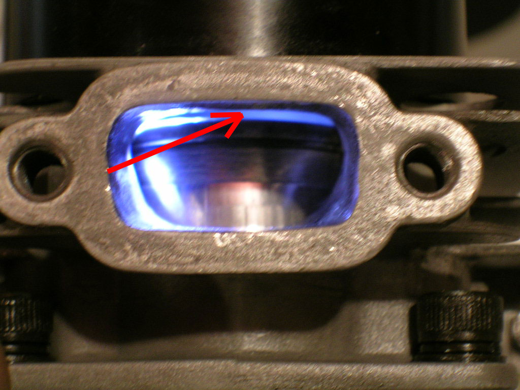
To start, rotate the crankshaft so that the top of the piston just closed the entire top of the exhaust port. You can use a small light inside the spark plug hole to make this easier. Move the crank back and forth to be sure you have the piston right on the edge of port closure/opening. As soon as you can no longer see daylight between the port roof and the piston, the port is closed. At this point take a reading on the degree wheel. * I usually make a mark on the wheel with a pencil.
In the picture, the red arrow indicates where the top of the piston should just close the top of the exhaust port. It is shown here with the port still slightly open for clarity.
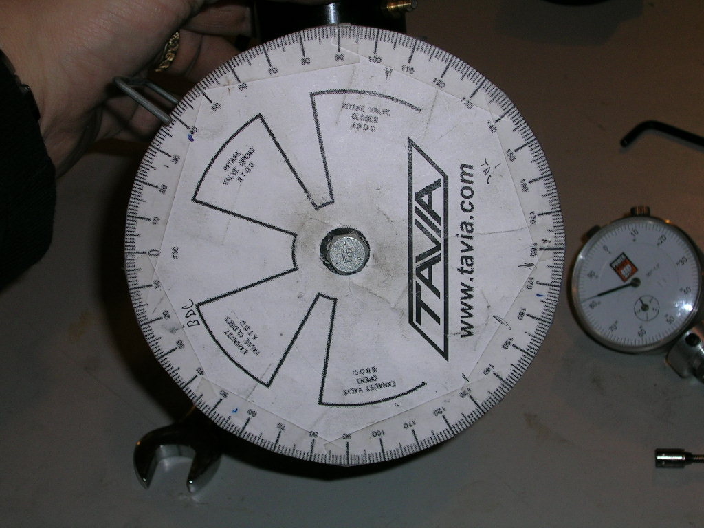
Now you want to rotate the crank so that the piston will start moving DOWN in the cylinder, passing through Bottom Dead Center (BDC) and back up towards the top of the cylinder to go close the exhaust port. Notice which direction you are turning the wheel when doing this. Depending on whether you were on an Up-Stroke or Down-Stroke when you first positioned the piston, you will be turning the crank clockwise or counter clockwise to accomplish this, but it makes no difference for the end result. The important thing is to note were you started on the wheel, where you ended on the wheel, and which direction you turned to get there! Bring the piston back to the same point where it is just finished closing the exhaust port and take the reading on the degree wheel.
All that's left to do now is count the degrees on the wheel from point A to point B, following the same direction you just turned the wheel and the result is your exhaust timing duration!
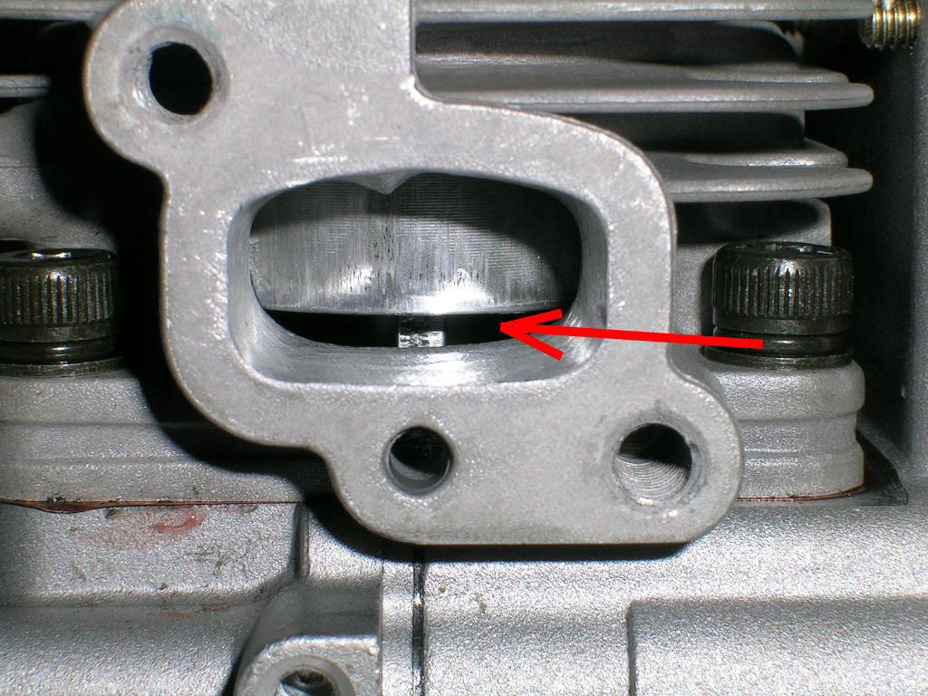 Measuring intake port timing uses the same basic technique but this time you have to position the piston so that the bottom of the piston just closes the intake port and take a reading on the degree wheel. Now rotate the crank so that the piston moves UP in the cylinder past TDC and back down to re-close the intake port. Again, notice which direction you are rotating the wheel to accomplish this. As soon as it closes the port completely again, take a second reading on the wheel. Count the degrees between point A and point B following the same direction you just moved the wheel and you have your intake timing duration.
In the picture, the red arrow indicates where the bottom of the piston should just close the bottom of the intake port. It is shown here with the port still slightly open for clarity.
Note: This article was not really intended to cover transfer port timing, but it can be measured using the same technique as the Exhaust Port timing, it is however more difficult to accurately see when the transfer ports are actually being opened and closed by the piston. I feel there are more accurate ways of measuring transfer timing which involve measuring from the base of the cylinder. The transfer port roofs are something that really should not be tampered with unless by very experienced engine builders, so for this reason I am not going into details on how to measure transfer timing in this article.
As you can see it really is quite simple to measure squish and intake/exhaust timing, and anyone can do it if they take the time to do it correctly and have access to a few simple tools.
Happy Boating!


