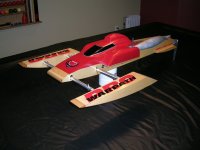
Product Review Article...
Our review of the Aeromarine Conquest Cat...* UPDATED 08-08-07
The name Aeromarine Laminates is probably one of the best known names out there when it comes to R/C boats. They make just about every type of hull you can think of in the R/C market. Over the years they have designed several catamaran hulls including the Jesse James, the Sprint Cat and the Avenger. Their latest cat, the Conquest is a modified version of the latter. It is a cut-down version of the Avenger with a redesigned top deck that incorporates more aerodynamic down force as well as better airflow. The cowl also features a higher top air scoop that conceals the typical Zenoah's spark plug.
The Conquest is a little bit shorter than it's predecessor due to the fact that it has been cut down to reduce freeboard. It is advertised as a 43.5" hull as opposed to 44" for the Avenger. I measured my Conquest and the overall length is 42 3/4" and the beam is 16". Overall height or freeboard (not including the cowl) is 5 1/2".
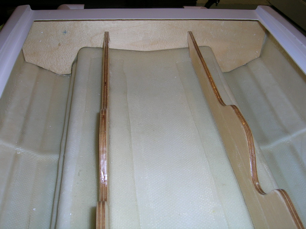
The construction of the Conquest is typical Aeromarine quality. The fiberglass work is excellent yet fairly light. The hull features marine grade 1/4" plywood stringers as well as a front bulkhead made of the same material which reinforces the top deck just forward of the cowl opening. The deck to hull seam is a shoebox type, held together with adhesive and fully taped with fiberglass from the inside for added strength. This last feature is somewhat new from Aeromarine and a good thing indeed. After thorough inspection, the gelcoat finish proved to be of very good quality. I also noticed that the stepped portion of the sponsons was layed up thick and strong and showed no signs of flexing at all, another positive point.
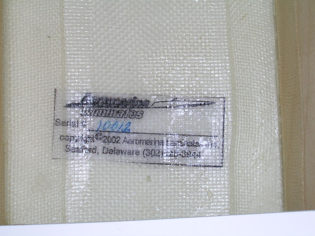
As with all Aeromarine hulls, the Conquest has a serial number laminated to the inside bottom of the hull and it is also delivered with a paper certificate of authenticity with matching serial number.
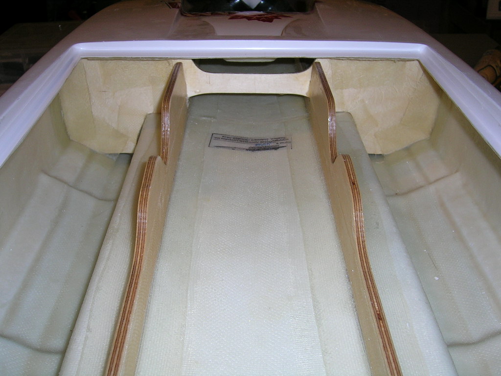
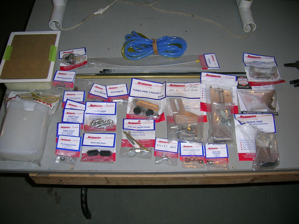
The kit I received from Aeromarine was the hull and hardware combo. It features just about everything you need to build the boat with the exception of the radio gear, engine, collet, mounts and exhaust. It also included a full setup sheet for setting up the boat with the Aeromarine hardware.

The Build...
Since I was waiting on a few items to be able to start the build, I decided to start with the graphics. After meeting the local Sleeman Breweries rep in town and explaining to him a little bit about my R/C boat hobby and the fact that I wanted to do the Sleeman Light them on a boat, he offered to supply me with the graphics files for their logos. All graphics were done using vinyl.
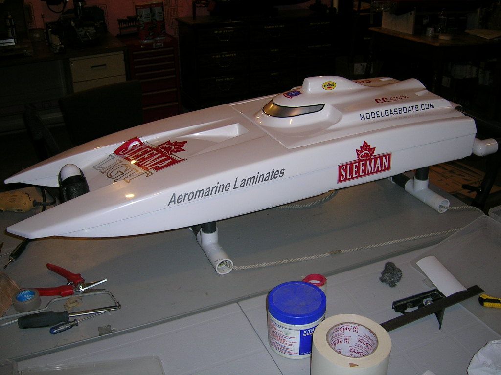
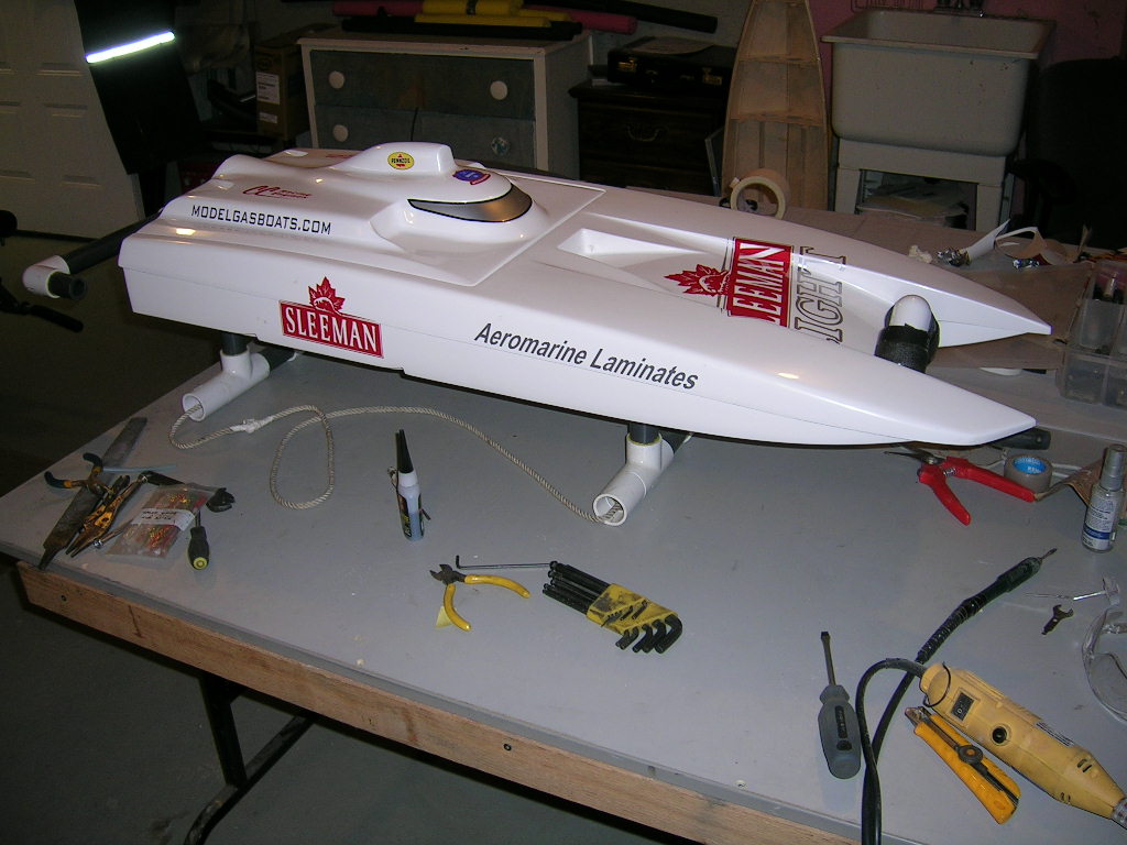
Because of personal preference I opted to use a gas bag instead of the supplied gas tank, which is a Sullivan BT16. I should also note that I did several things in this build that deviated from the setup sheet. I have built Avengers in the past following the supplied setup instructions and they performed quite well, but I wanted to try something a little bit different this time...you will see what I mean as you read on!
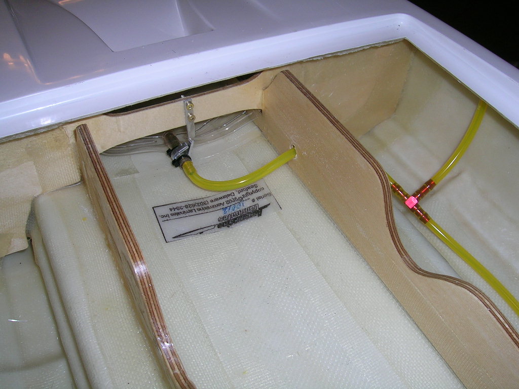
To hold the gas bag in place I made a small aluminum bracket that is screwed on to the bulkhead and grips tightly around the outlet of the bag. This prevents the bags from moving back or forth in the boat. The bag itself is mounted forward of the bulkhead. I used a 1000ml setup from American RC Boats . I like the 1000ml size because I often fill it right up to add extra weight up front in very rough/windy conditions. In calmer waters, I can simply add less gas loosen up the front of the boat a little. In all honesty however, after much testing, I ended up moving the bag back under the engine to keep most of its weight as close to the C.G. (center of gravity) of the boat as possible. In most of the pictures in this article you will see the bag mounted forward of the bulkhead, but this is simply because all these pictures were taken before the actual testing took place.

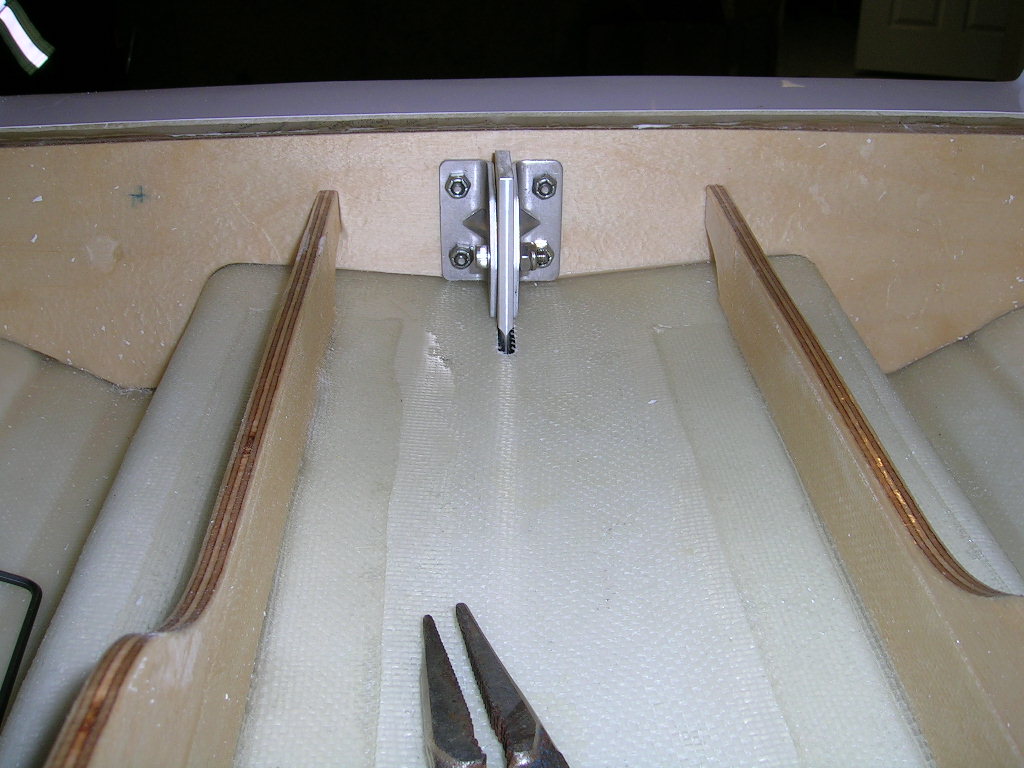
I decided to mount the strut from inside the transom on my Conquest. This is where things get very different from the instruction sheet I received with the hull! I wanted to do this setup using only the supplied Aeromarine hardware. After some thought and measurements, I figured it would be better if I swapped the strut and rudder brackets. In other words, I would use the rudder brackets (which are shorter) to mount the strut to the inside of the transom. The longer strut brackets would be used to mount the rudder.
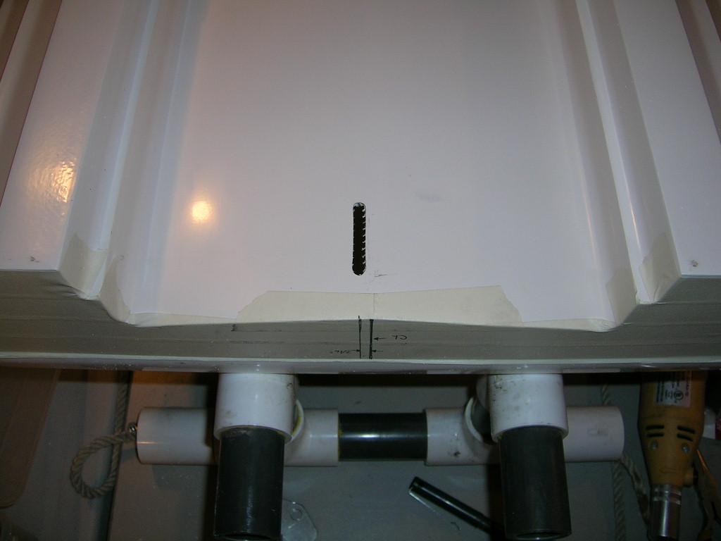
I marked the transom for the centerline and the rudder centerline. The strut centerline was marked 3/16" to the right (starboard) side of the hull centerline. Mounting the strut offset like this helps counteract propwalk without shimming. I then marked the underside of the tunnel and cut out a slotted opening for the strut blade to pass through. I mounted the strut (which has a skeg as can be seen) to the inside of the transom using the short brackets.

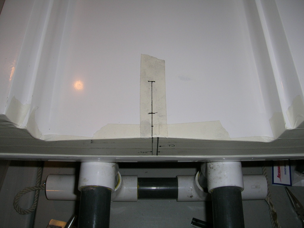
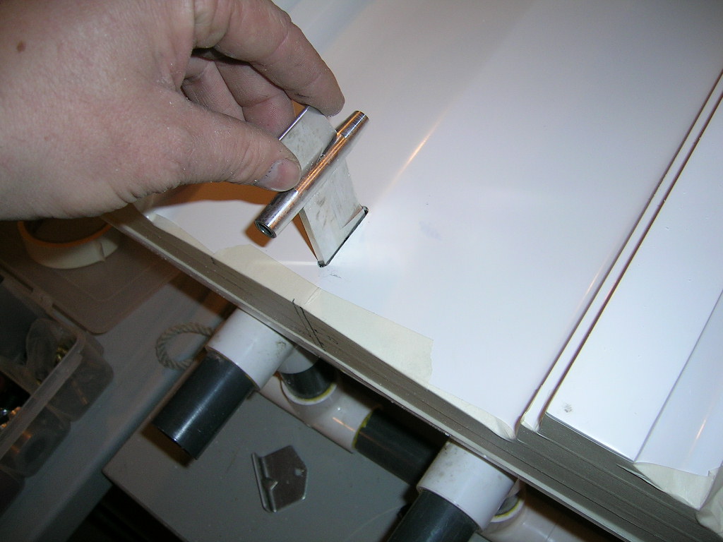
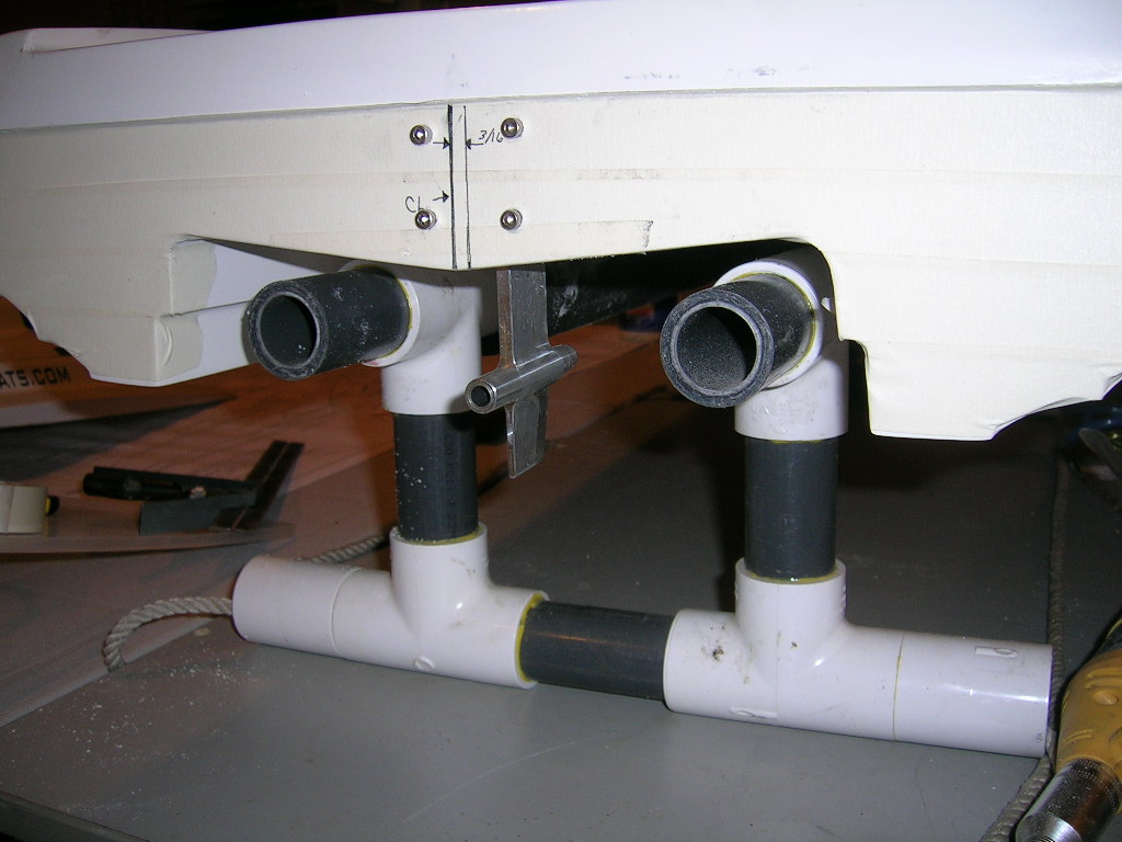
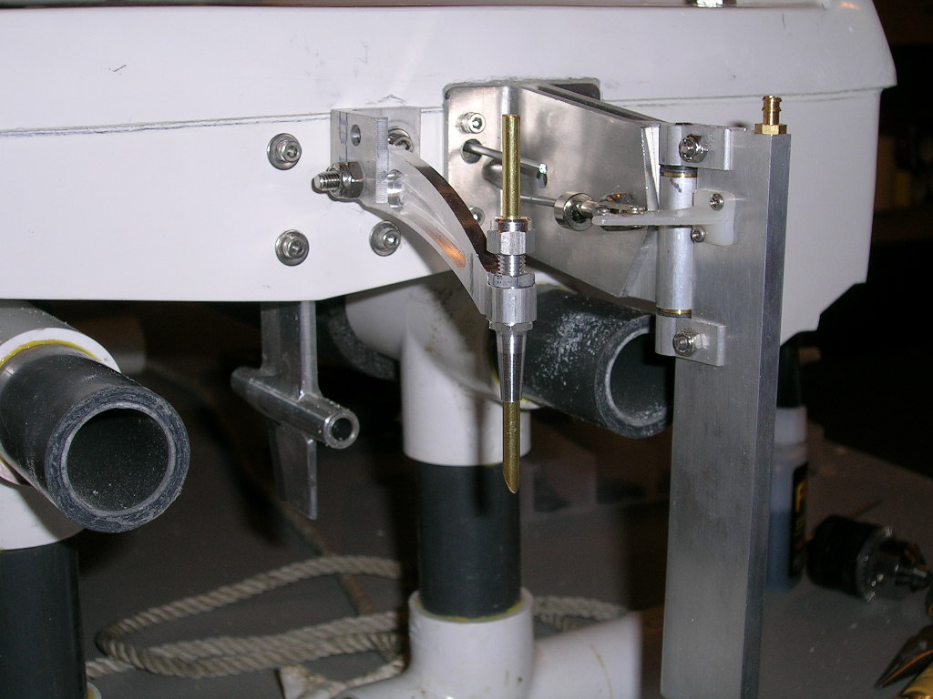
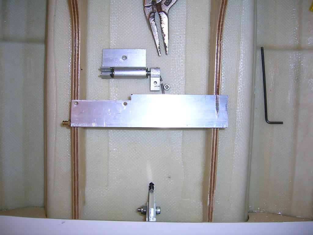
As mentioned before, I used the strut brackets to mount the rudder blade. To get the rudder at the proper distance from the transom I decided to trim the brackets just past the first mounting hole as seen in the pictures. I also modified the rudder blade slightly by trimming it so its leading edge lined up with the centerline of the pivot pin. I did this using a mill, but it can be done with a hacksaw and a file. I then assembled the rudder blade hardware and mounted the assembly to the brackets. Since the brackets are made on an angle I had to decide if I would mount them angling upwards or downwards. After taking some measurements, I decided that the rudder would be better positioned if I mounted the brackets angling downwards. To allow for the brackets to clear the tunnel I trimmed a little bit of material from the top deck lip. Below are some pictures of all these steps.

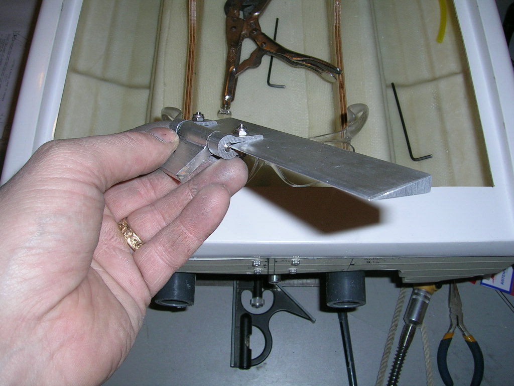

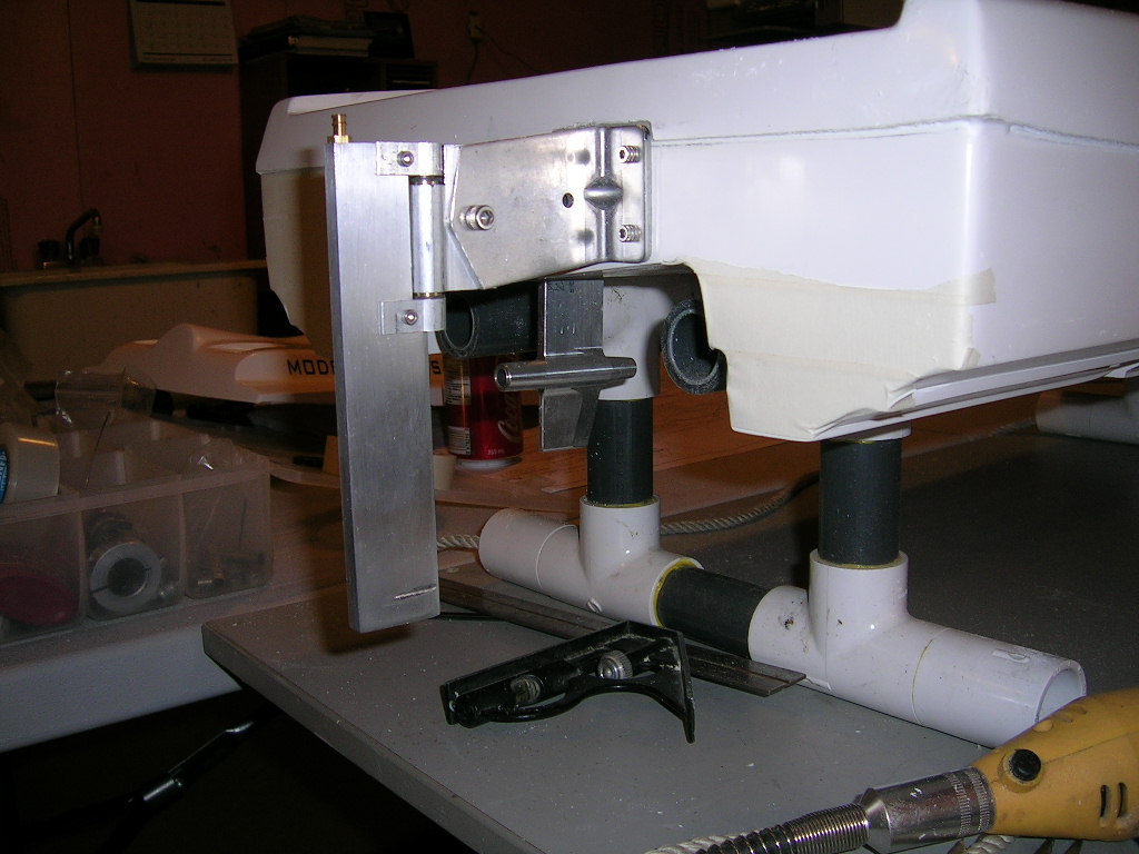
To mount the propblast water pickup I made a small bracket from a piece of angled aluminum. The bracket is held to the transom using the upper right side strut mounting bolt. This positioned the pickup at about 2 O'clock in respect to the prop. The tip of the pickup is about 1" above the prop centerline.
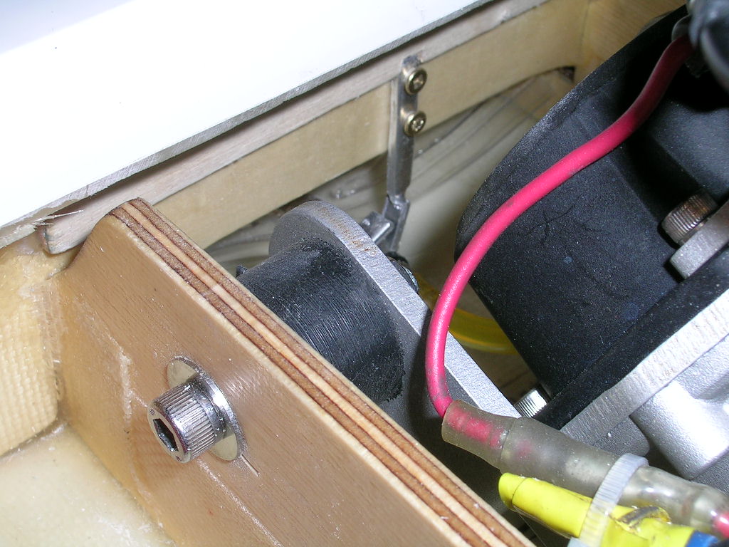
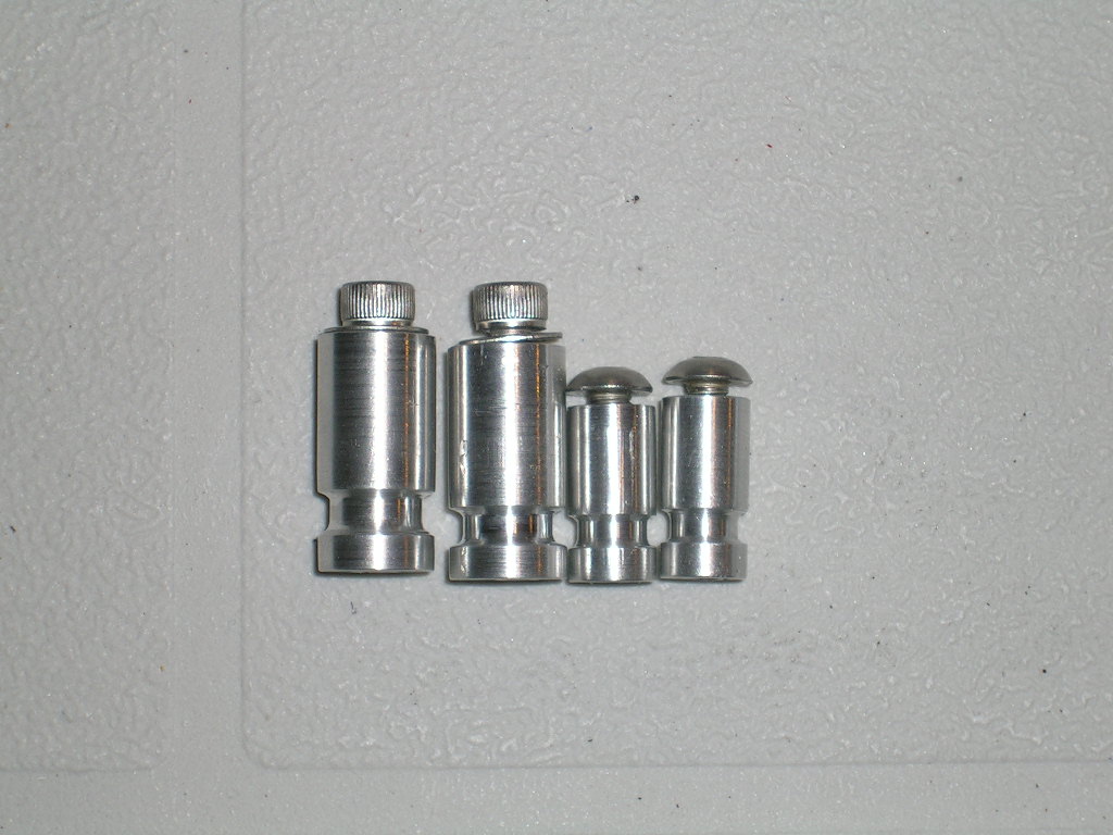
The radio box installation is pretty straight forward. I used the included servo trays from Aeromarine Laminates. I epoxied a piece of 1/4" plywood to the bottom of the box and waterproofed it. This allows for the tray screws to have something to bite into while remaining watertight. The only thing I did a little bit differently was the way I actually mounted the box in the hull. Because of the fact that the strut is mounted inside the hull, I needed a radio box setup that allowed for quick and easy removal and re-installation. For this I machined some mounts from aluminum rod. The mounts consist of 4 rods, 2 of which are mounted to the box with cap head screws from the inside (with some silicone sealant as added protection between the mounts and the box). The other two mounts are screwed to the stringers of the hull. The stringers are then grooved for the box mounts to lay into, and the box held in place with 2 simple Orings. The pictures explain it much better than words can! For the record, I found that the Orings I had didn't hold the box firmly enough to my liking, so I now use tie wraps instead. I did not invent these mounts...I actually borrowed the idea from Carlo at CC Racing Engines. You can now purchase these mounts from CC Racing Engines , but at the time of building this boat, the mounts were not yet in production, thus the reason for machining my own.
To ensure the ease of pulling the radio box, I also used split throttle and rudder linkages, held together with wheel collars. To pull the box I now only have to loosen the wheel collars and remove the two tie wraps (or Orings) and out comes the box. After adjusting the strut, I just drop the box back in and tighten the collars, install tie wraps and I'm ready to go!

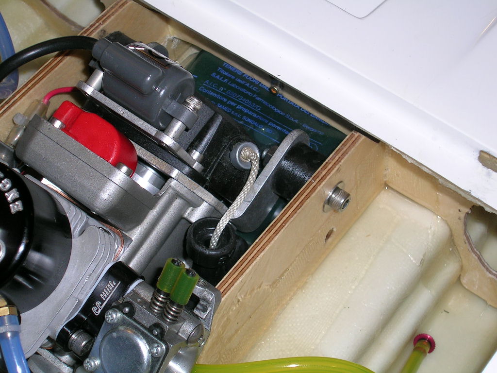
I mounted the engine as far forward in the hull as I could while keeping the front mounting bolts easily accessible. Since I use mostly Hypertorque style mounts, this limited how far forward I could go. With some other types of mounts you could possibly get the engine even further forward, which would be a good thing, but I really love these mounts so I had to live with the placement.
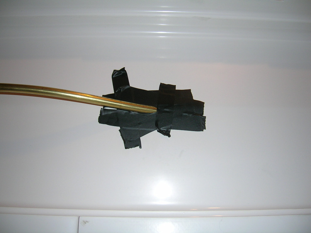
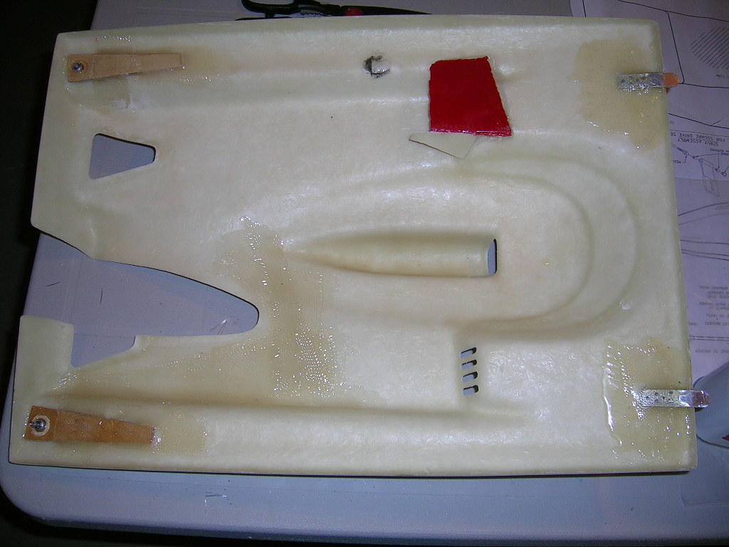
I installed a piece of 1/4" rod in the engine's collet to serve as an indicator for where to cut the hull bottom for the stuffing tube. After cutting the slot, I installed the stuffing tube so it fit in the strut and lined up with the engine collet (again using the piece of 1/4" rod in the collet as a guide). I taped around the tube and slot from the underside of the hull and glassed in the tube.
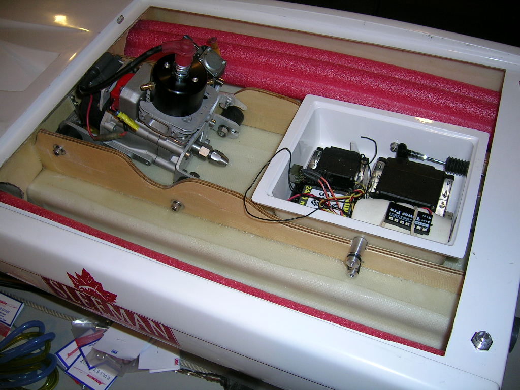


For mounting the cowl I used the supplied cowl locks on the back and glassed in two aluminum tabs in the front. The tabs slip into slots cut out of the front hatch opening. The area where the tabs are fixed to the front of the cowl was reinforced with extra layers of fiberglass using West Systems epoxy. I also doubled the back hatch opening and cowl where the cowl locks fit. To do this I used 1/8" plywood and West Systems epoxy.


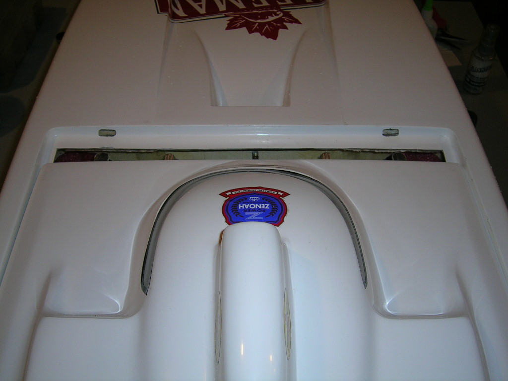

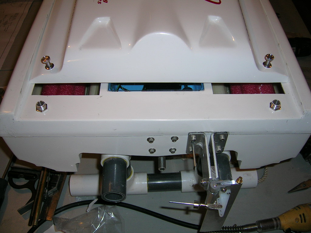
I also used some scrap pieces of fiberglass to make deflectors inside the carburetor side air opening in the hatch to ensure no water would be ingested in the carburetor when following other boats. I also blocked off the top portion of the opening in the front bulkhead so that any water coming in from the front deck air opening would be routed under the engine and not splash off the pull start and possibly into the carburetor. Now that the gas bag has been moved to under the engine, that entire opening is blocked off and any water coming in from the front opening will have a very difficult time finding its way to the carburetor. So far this has worked quite well. If it becomes an issue at some point, the front air opening will be sealed up completely.


The cowl was then trimmed for the tuned pipe to exit and floatation was added. I used metal mesh in the cowl's rear air exits and the front deck air opening. The screen is available from auto repair shops. It is aluminum mesh made by Bondo...it's called "Body Patch".
I made my own tuned pipe mount from pieces of flat and angled aluminum. I cut out slots in both side air intakes in the cowl and opened up the top air intake scoop. I made holes in the bulkheads for pool noodles to pass through. The pool noodles run from the transom to the tips of the sponsons. They serve as floatation and lead weights were secured inside the tips to add weight to the front of the boat.

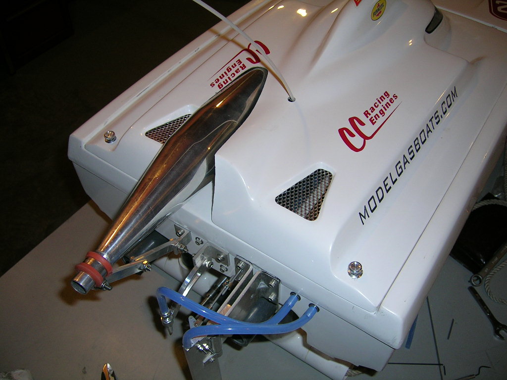
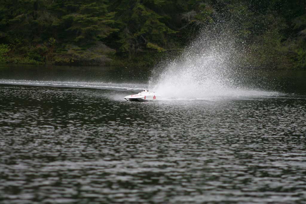
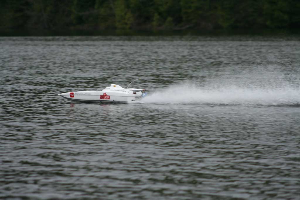
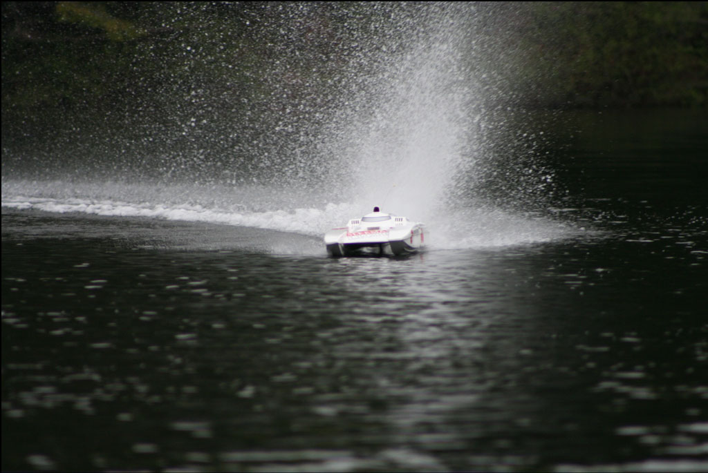
Here are some still and action pictures of the finished boat. There is also a picture of my friend driving the boat so I could take pictures.
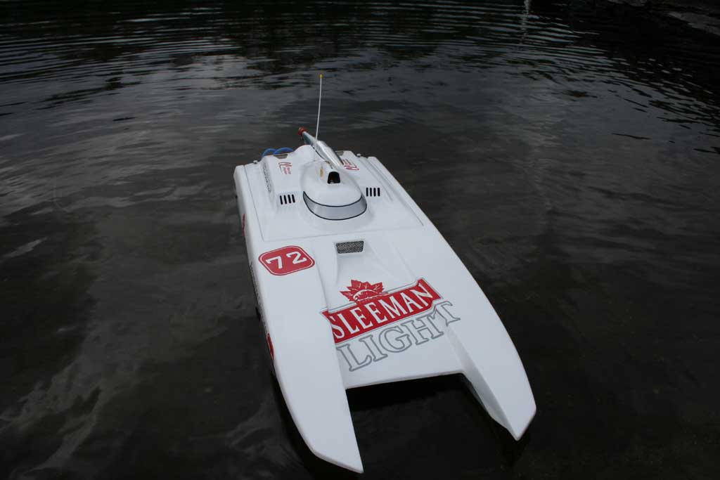
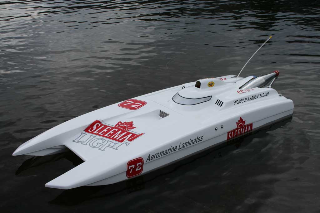
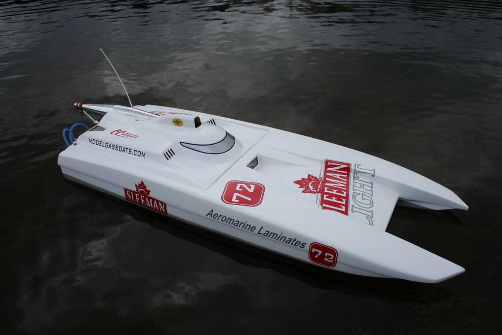

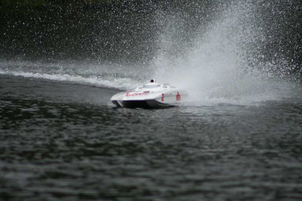
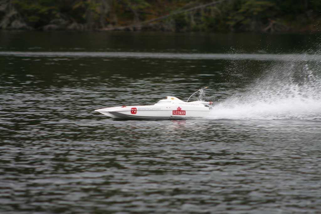





At the lake...
The first time I ran the boat I had the strut set at about 3/8" above the sponsons and the boat ran much too wet. After some trial and error I ended up with the strut lower with a little bit of positive angle. The boat was getting faster and faster but blew over as soon as it hit a good wake going into a head wind. I started adding weight to the sponson tips and readjusted the strut until I got the boat to run like I wanted it to. I also noticed it was digging hard into the turns and would loose way too much speed, so I played with the rudder angle at this point. After three testing sessions I finally found the settings that I think will make this boat a great heat racer. Here are the details. I am providing this information for reference only. As they say, "take it or leave it". My Conquest runs great setup like this! Boat was GPSed at near 60mph in rough conditions and performed flawlessly.
Weight of boat RTR with 1000ml of gas: 17.5 lb
Weight in sponson tips: *edit: 8 oz in port side, 6 oz in starboard (in tips)
C.G. (with gas): *edit: 35%
Strut Depth: * edit: optimum strut depth has ended up being 9/16" above sponson bottoms (center of drive shaft at strut, to flat surface that boat is resting on...make sure the boat is sitting tight against the table to adjust strut)
Strut Angle: 0 degrees (parallel with riding surface)
Strut Offset: 3/16" to the right (starboard) of centerline
Prop Trailing Edge: 1.5" from transom
Prop Used: 6717/3 - 380 from The Propworks
Rudder Leading Edge: 3" from transom
Rudder Angle: *edit: kicked back about 1-2 derees (away from transom)
Engine: CC Racing Engines full mod Zenoah 260 PUM
Tuned Pipe: CC Racing Engines Powermaster Pipe
*Please note: video is of the first runs with initial setup. With the changes noted above, the boat turned out to be much faster and holds speeds better in the turns. Has performed very well over all.
Watch Video!
You can get a dowloadable version of the video by CLICKING HERE .
Final thoughts...
- good quality lay-up with taped seam
- good quality gelcoat finish
- scale appearance
- great performance
- very complete hardware package when ordered as hull and hardware combo
- good value
- included setup information that will allow even beginners to build a good boat
- engine completely concealed under the cowl
- I only wish it were easier to locate the engine further forward to avoid having to add weight to the front, but this can probably be accomplished by using different engine mounts.
- Although of good quality, I think the hull could actually benefit from slighty heavier lay-up for use as a heat racer
All in all this is another great boat from Aeromarine Laminates. It is currently winning its share of races and I am certain it will continue to do so. I have always been a fan of the Avenger and the Conquest is even better in my opinion.
Happy Boating!
Contact Information


