Tech Article ...
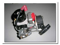
A step-by-step guide to disassembling and re-assembling your Zenoah engine...
I've been getting alot of Emails from people asking questions about how to disassemble and re-assemble parts of Zenoah motors. Up until now, I have always tried to help out by answering individual questions by Email, but it is usually very difficult to put into words some of the procedures, so I decided to do an article that will cover a complete tear-down and re-assembly of a Zenoah motor. The motor I used for this pictorial is a Zenoah G260PUM and is built of some parts that were worked on for testing purposes, so please note that some parts aren't totally stock, but the basic procedures are unchanged and would be exactly the same with a stock motor. The steps outlined bellow would also apply to all Zenoah PUM motors. Please note that for other series Zenoah motors, such as PUH, PU and RC some steps would differ. So keep this in mind if you are working on these motors. I would also like to note that some methods used are not the ONLY way of doing things, but merely one way of doing it. For example, heating cases with a torch to drop bearings is not necessarily to most technical way of removing the bearings, but when done carefully it works quite well. The use of a magnetic heater and heat pencil for example could be considered a better method, but since not everyone has access to such tools, I decided to try and illustrate methods that most any modeller can perform.
One thing I find important to note is that it took me ALOT longer to actually write this article than it did to do the actual teardown and re-assembly of the motor! There is nothing complicated in the mechanics of doing this kind of work. Just be carefull and take your time.
Before you get started, you should setup a space on a clean work table and have the required tools ready. It is also strongly recommended that you have the required new parts for re-assembly, such as bearings, oil seals and gaskets. If not removing the bearings and/or oil seals from the cases, they can be re-used, but it should be noted that if you try to remove them they will most likely need to be replaced. In any case, when you go this far in disassembly, its probably a good thing to replace these parts anyway. As for the gaskets, I have never believed in re-using gaskets (except maybe for the copper ultra thin gaskets) and I would say that it is a must to have new ones on hand to replace any that you remove during the process.
So lets get to it! The basic tools you will need to do the job following the step herein are:
- a set of metric and standard allan wrenches
- snap ring pliers (optional)
- phillips screwdriver (for stock fasteners on motors)
- a flathead scewdriver is handy to remove to oil seals
- a small pair of side cutter pliers (snips)
- small pliers (channel lock type prefered)
- an adjustable wrench is always handy to have around too.
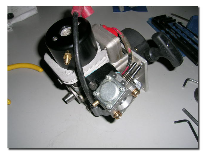
Pic 1: motor we are going to work with (spark plug already removed)
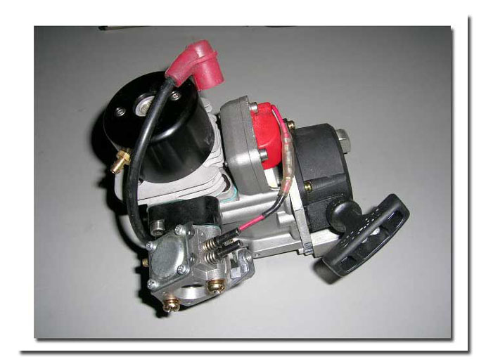
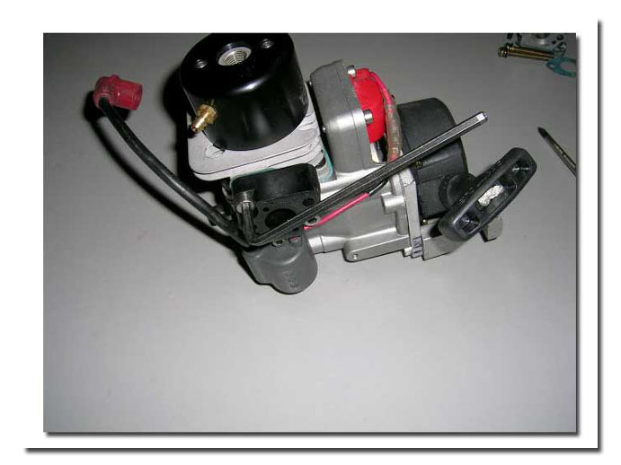
Pics 2 and 3: Remove the two screws holding the carburetor to the insulator block. On stock motors these are Phillips head screws. Note that the carburetor pictured here is a Walbro 257. The stock carburetor is a Walbro 644. Steps are the same. Also remove the gasket behind the carburetor.
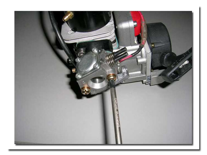
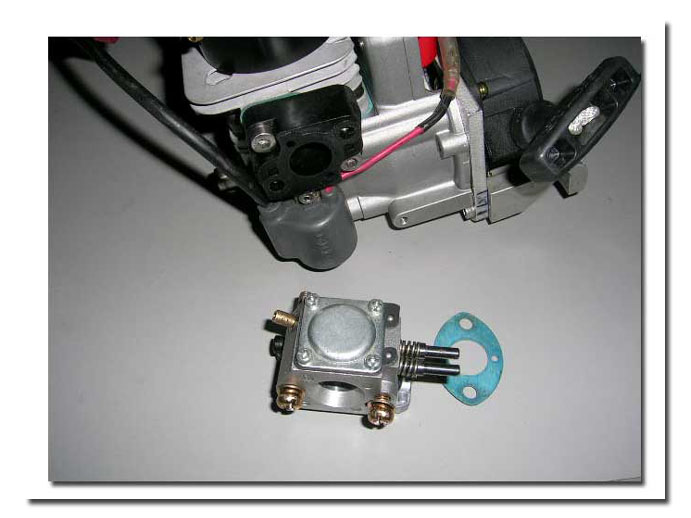
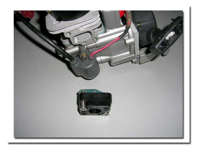
Pics 4 and 5: Remove the two screws holding the insulator block to the cylinder. There is a gasket between the insulator block and the cylinder. Remove it.
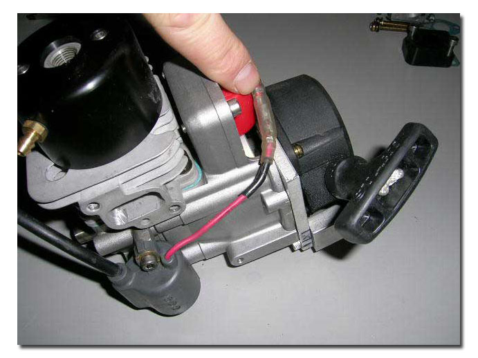
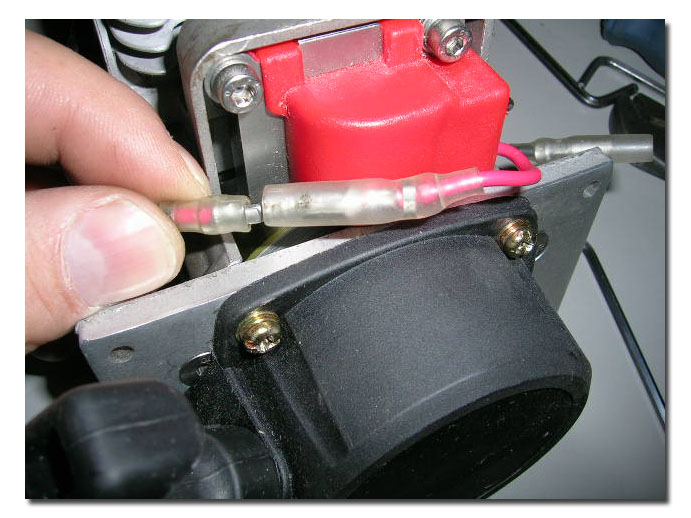
Pics 6 and 7: Unplug the red wire between the red and grey coils. Hold both sides of the connector firmly when pulling to seperate them in order to prevent pulling the wire out of the connectors.
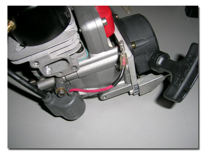
Pic 8: Remove the two screws holding the grey coil to the side of the crankcase. Stock screws are Phillips head screws. Remove the grey coil.
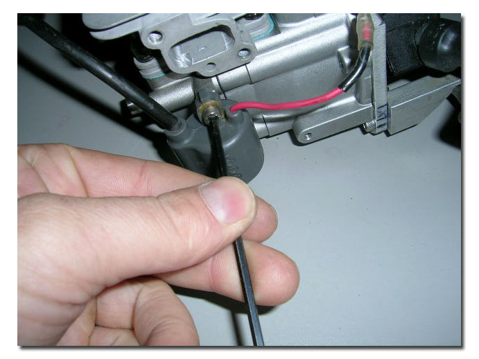
Pics 9 and 10: Remove the four screws holding the pull starter. Remove the pull starter.
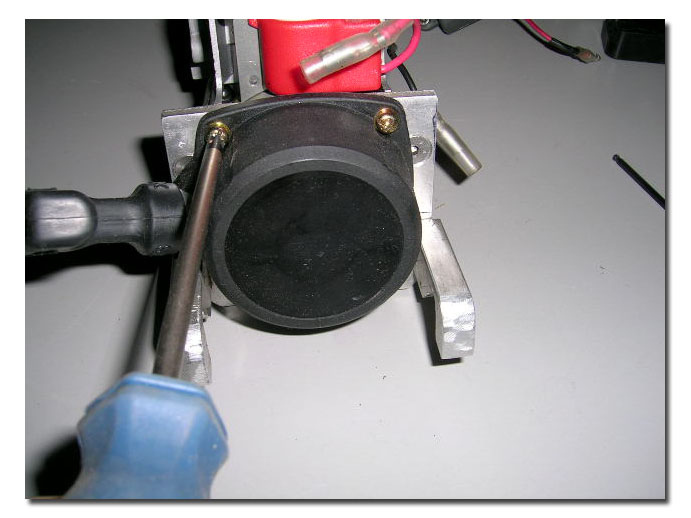
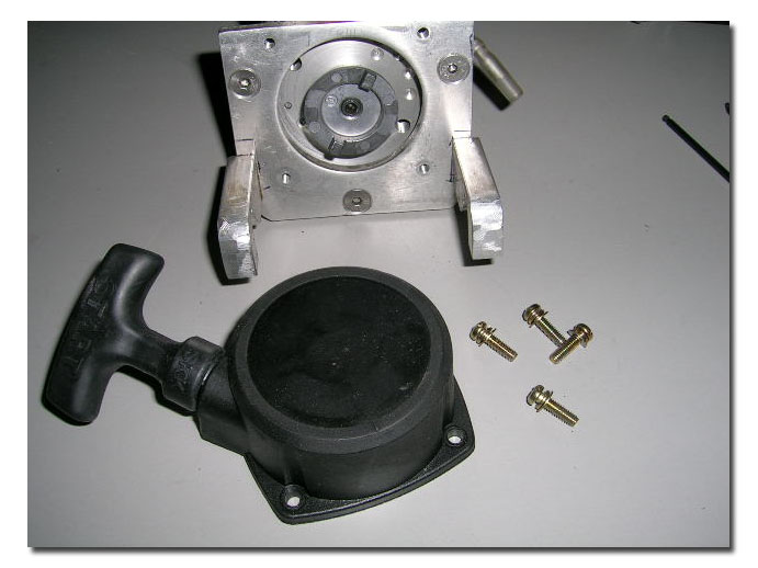
Pics 11 and 12: Remove the three screws that hold the motor's backplate. On stock motors these are also Phillips head screws. It is sometimes fairly difficult to remove these, and the head can strip easilly so be careful. If you do strip one (been there) use a rotary tool with a cutting disc and cut a flat slot in the head and remove the screw with a good flat tip screwdriver. Notice that the backplate pictured here has been modified somewhat. I had to make some emergency mounts for a race and actually kept them. I don't use them anymore but still keep them as backups.
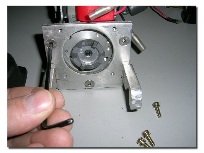
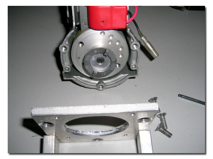
Pic 13 : A stock backplate.
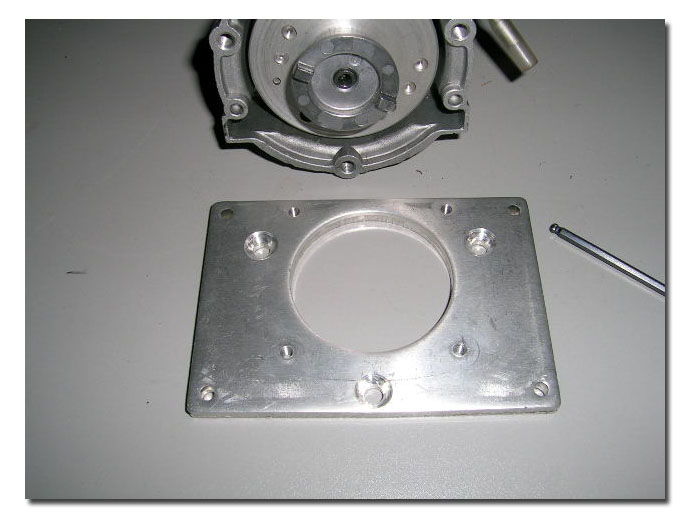
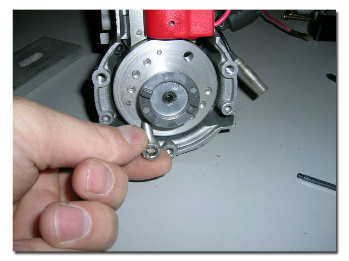
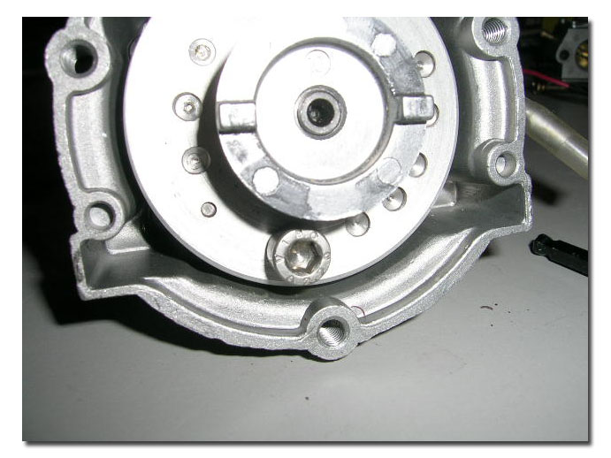
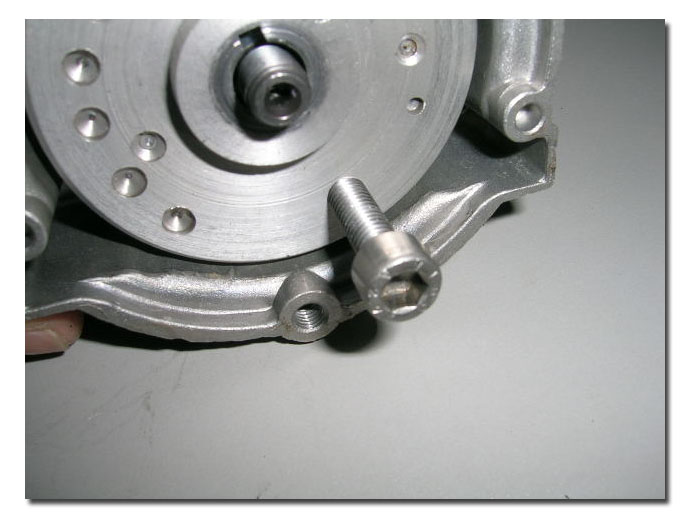
Pics 14 and 15: This is how I hold the flywheel in order to remove the pulley that holds it on the crank. There are different methods of doing this, including stuffing small rope in the cylinder or using a piston stop tool, but these methods rely on the piston to hold the crank in place when you are applying force on the pulley to remove it. Doing this can actually lead to the crank being forced out of allignment. I simply insert a 6mm allan bolt into one of the puller holes in the flywheel and position the flywheel as pictured. The bolt has to be long enough to go through the flywheel and protrude in the back. The bolts I use are 30mm long from under the head to the tip of the thread, and fully threaded. As you try to turn the flywheel counter clockwise, the screw will butt up against the crankcase casting behind the flywheel and hold it enough for you to remove the pulley. This same method is used to re-install the pulley later on.
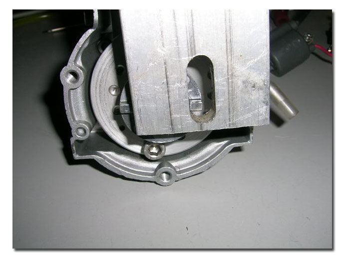
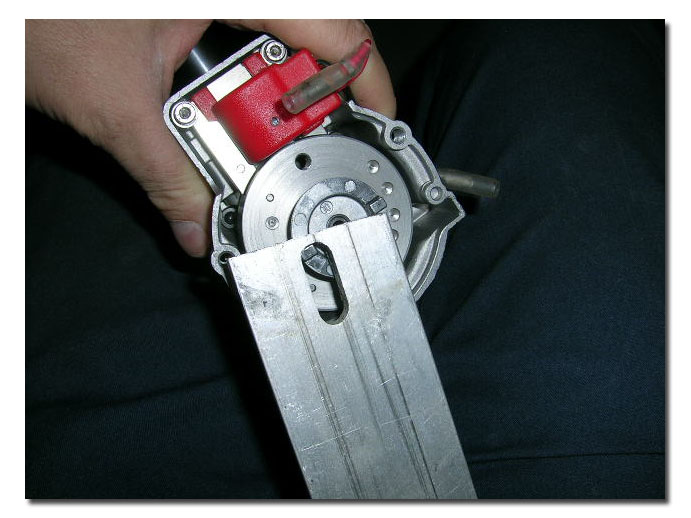
Pics 16 and 17: Shows what I use to remove and install the pulley. You can actually purchase a tool for this from Zenoah, but this works just fine. Its actually just a 2" wide piece of aluminum flat bar 1/2" thick with a slot cut into it. One of the ears of the pulley fits into the slot and the side of the bar rests against the other ear providing ample grip to unscrew the pulley. In future "Hobby Machinist" articles I will try to illustrate methods of making a few handy tools for engine work, including a tool similar to this one (but nicer) and a flywheel puller.
Pic 18: Pulley removed. Flywheel ready to be removed from crankshaft.
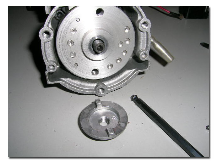
Pics 19 and 20: Remove the two screws holding the pickup coil (red) in place over the flywheel. The stock bolts are Phillips head screws.
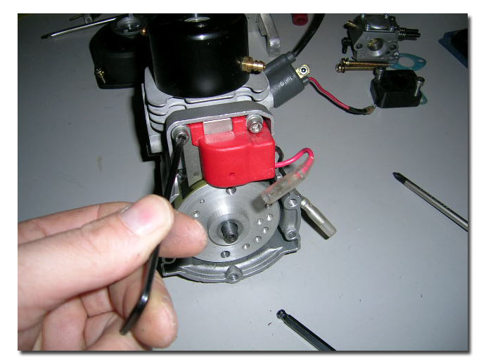
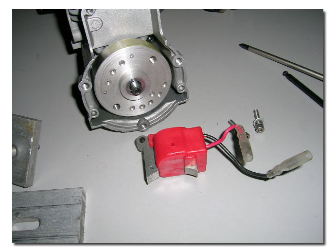
Pics 21 and 22: Shows the "puller" I use to remove the flywheel. Its simple and effective. It is simply an aluminum plate 1/2" thick with two holes drilled in it to accomodate the two 6mm thread bolts that will be used to pull off the flywheel. Spacing the two 7mm diameter holes 47mm center to center will do the trick. Insert the bolts in the plate and thread them into the two matching holes in the flywheel. Thread them in slowly and evenly until the plate butts up against the crankshaft end. Hold the plate with one hand and tighten each bolt a little at a time so the pulling force is even on both sides. You will have to hold the plate firmly and apply sufficient force on the bolts. You will hear and feel a sudden "pop" when the flywheel comes off the cranshaft taper. Then simply pull it off by hand and remove the puller.
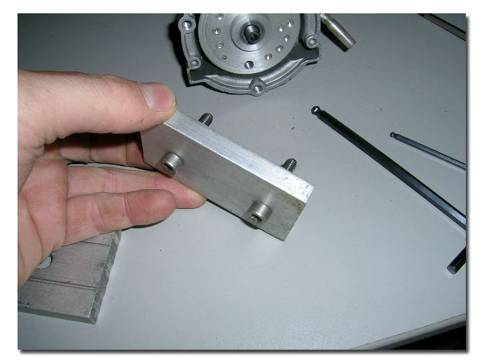
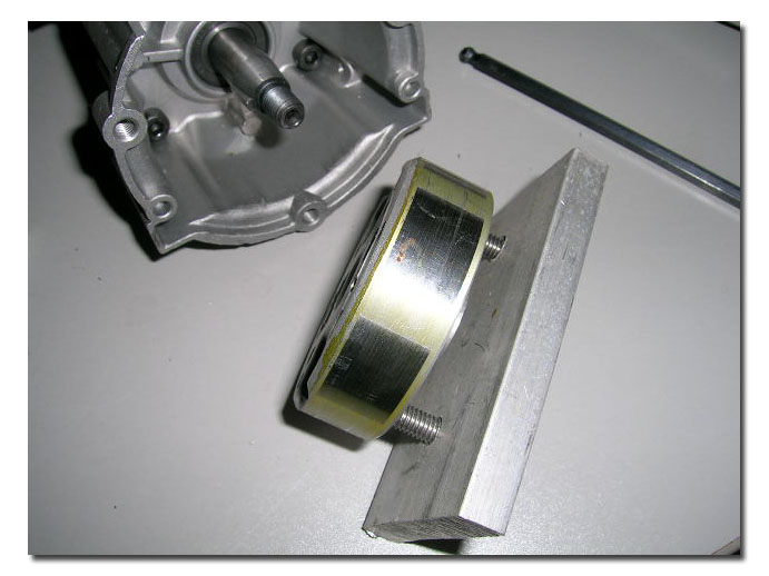
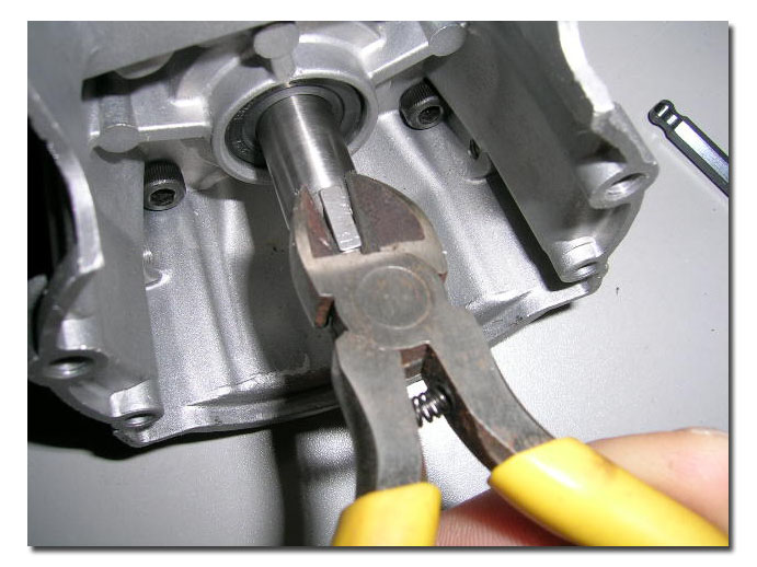
Pics 23 and 24: Using the side cutter pliers, grip the flywheel key and pry up to pull it out of its keyway. The key is made of fairly soft metal, special care should be taken to try not damaging it. If you damage it (burrs) file it clean before re-assembly.
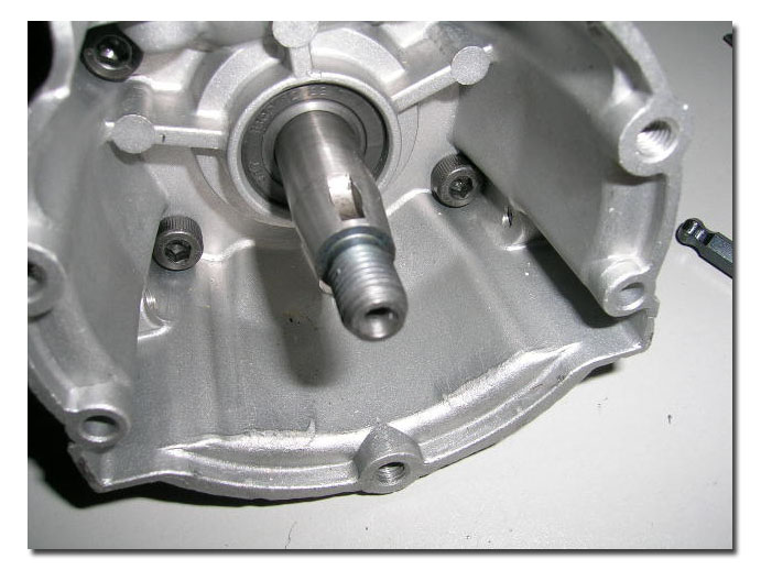
Pics 25 and 26: Removing the clyinder. Loosen and remove the four allan bolts holding the cylinder down. Genlty remove the cylinder from the base. You might have to pry a bit to loosen the cylinder off the base if the gasket is "stuck". Once you feel it let go, lift straight up. Grab hold of the piston as soon as the cylinder is high enough to do so to avoid letting the piston drop out.
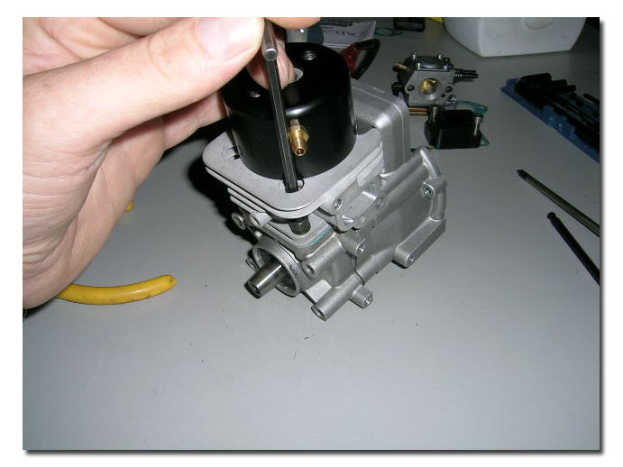
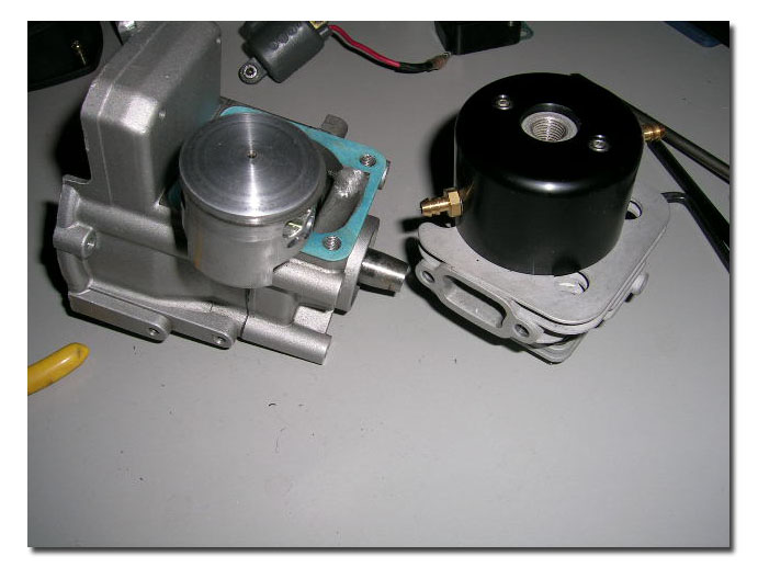
I did not remove the piston when I did this rebuild, but this is a fairly straight forward task that I will try to explain. There are two snap rings (one on either side) holding the wristpin in the piston. To remove the piston you must remove the wristpin. To remove the wristpin you remove the snap rings ( only have to remove one actually) and push out the wristpin. Hold the piston while doing this. Then you carefully lift the piston off the connecting rod and lay it aside. The bearings in the connecting rod (piston end) are now free to be removed, or fall out! Carefully remove the two spacer washers (one on either side of the bearing) and slide the needle bearing out of the connecting rod. You have to take them out or they will fall out. Happilly the needle bearing is a caged type!
To remove the ring from the piston find the break in the ring, at the retaining pin and spread the ring open enough to lift it over the piston crown (top). DO NOT pry! It must be out of the ring groove, all the way around before lifting. If you pry, it WILL break. If you spread it too much, it will also break! If you are going to remove the ring, have at least 1 spare one handy just in case.
Pic 27: Remove the four allan bolt that hold the crankcase halves together. These are at the flywheel end of the motor.
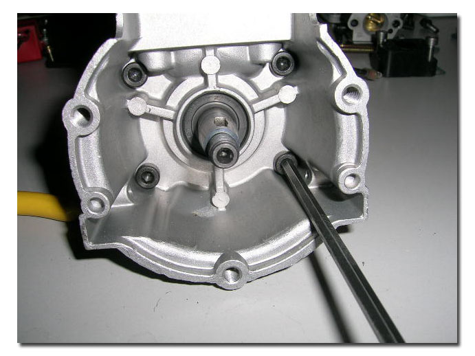
Pic 28: Shows the crankshaft still inside one of the crankcase halves. (some signs of seal leakages were obvious here)
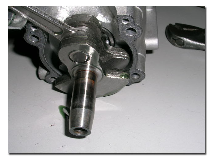
Pics 29 and 30: Crankcase halves and crankshaft removed. * Please note: you will notice that the piston pictured is not stock, and I do not recommend doing such mods to your pistons...this was a test engine, so modifications seen here are not necessarilly good!
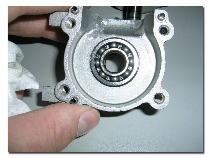
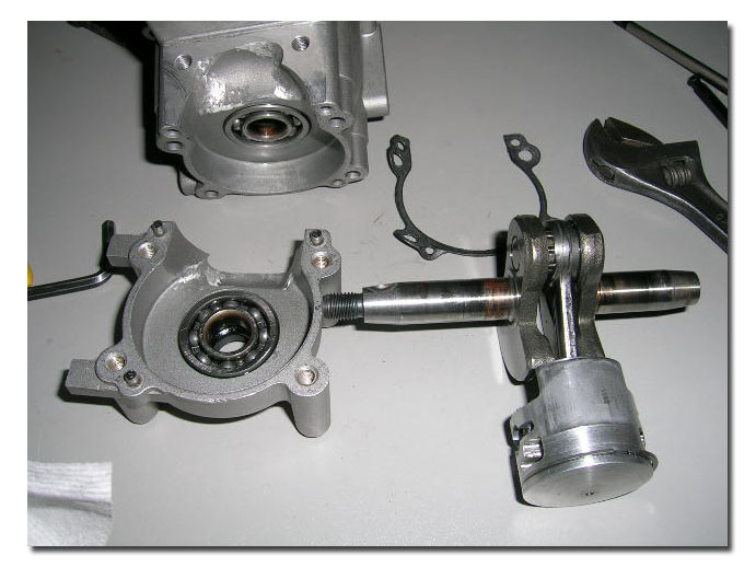
Pics 31 and 32: Removing the large oil seal (output end). I pry it out part way with a flat head screwdriver then push it out from the other side using the same screwdriver. There are so many different way of doing this, but this works for me. I almost always destroy the seals taking them out this way though, but I would never re-install old seals in a motor anyway, so I don't take any special care in removing them. Worth noting however is to take special care not to damage the seal seat in the crankcases however. It is easy to burr the inside of the crankcases when removing the seals so be carefull. If you do happen to damage them, carefully file them smooth using whatever you can to do so. Do not modify the bore. You want the new seals to fit in properly and seal the way they should: they not only seal on the crankshaft, but also in the crankcases.
*** Carlo Catalanotto of CC Racing Engines was kind enough to submit an article on Bearing and Seal Installation...at this point you may wish to go read his article and use his method for dropping and installing the bearings and seals. Below is explained using a small propane torch. Carlo uses a much safer and more controlled method with incorporates the use of a small toaster oven. You can read the article by CLICKING HERE.
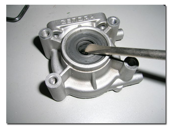
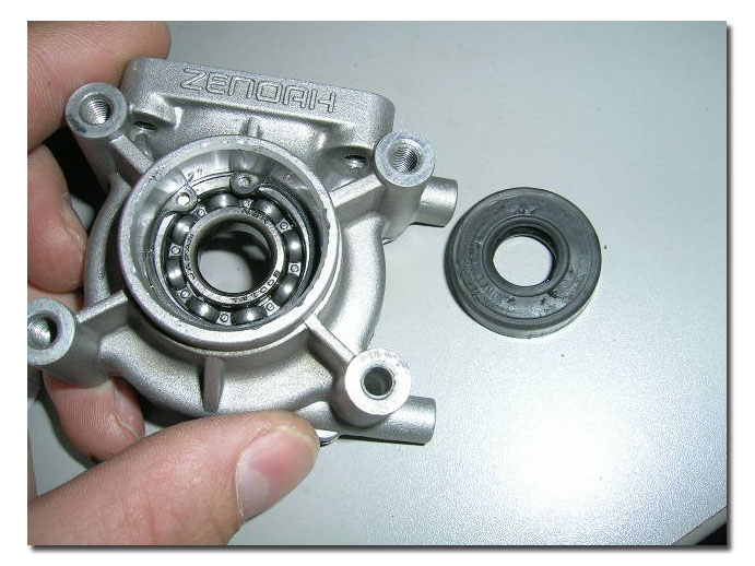
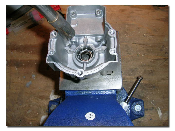
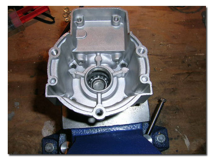
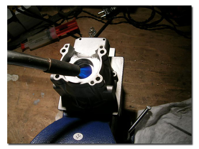
Pics 33, 34 and 35: Dropping the bearings. Setup the case (with oil seal removed) on a fireproof surface with bearing side down. With a propane torch, heat case evenly around the bearing, taking care not to stay in one place long and not heating directly on the bearing. You want to heat the aluminum around the bearing enough for it to expand. The aluminum will expand faster than the steel bearings (especially if you do it right and don't direct the heat on the bearing itself) and the bearing will simply fall out. Notice the cirlclip or snapring in the output side case. This serves as a stopper for the bearing.
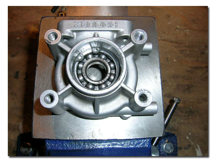
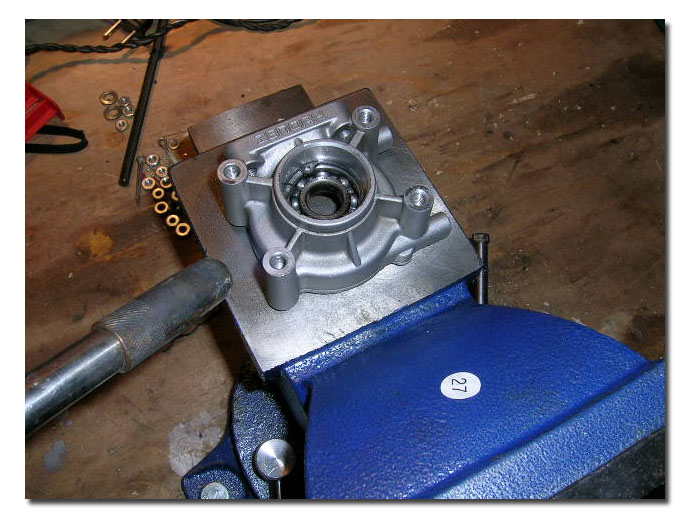
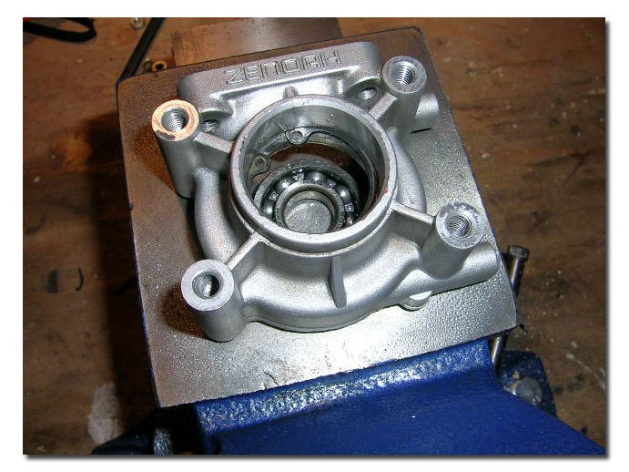
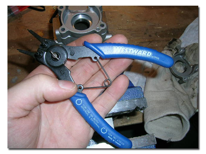
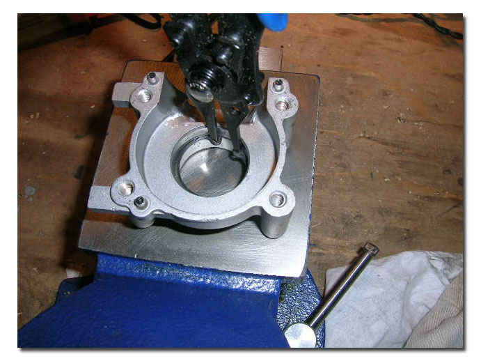
Pics 36 and 37: If you want/have to remove the snap ring you will need this type of tool.
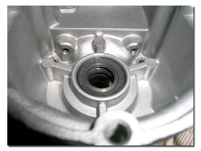
Pics 38,39 and 40: Removing the small oil seal (flywheel end). Notice there is no snapring stopping the bearing in this case. The case itself has a lip for the bearing to butt up against. Thus the reason for the smaller oil seal since the bore is smaller on that side.
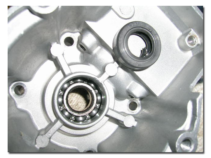
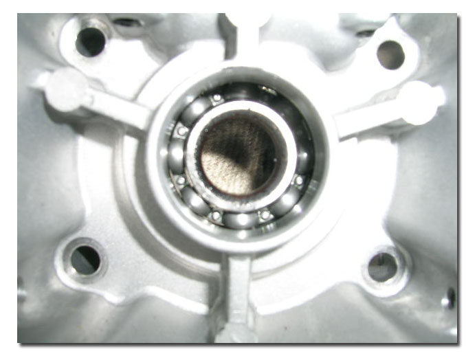
Pics 41 and 42: Drop the bearing, same method as the other bearing, by resting the case bearing side down on a fireproof surface and heating it with a torch. Aluminum can easilly be melted, so a propane torch is the most heat you would want to use, and avoid heating the same area consistently.
Pic 43: Old bearings, seals and gaskets that will be replaced.
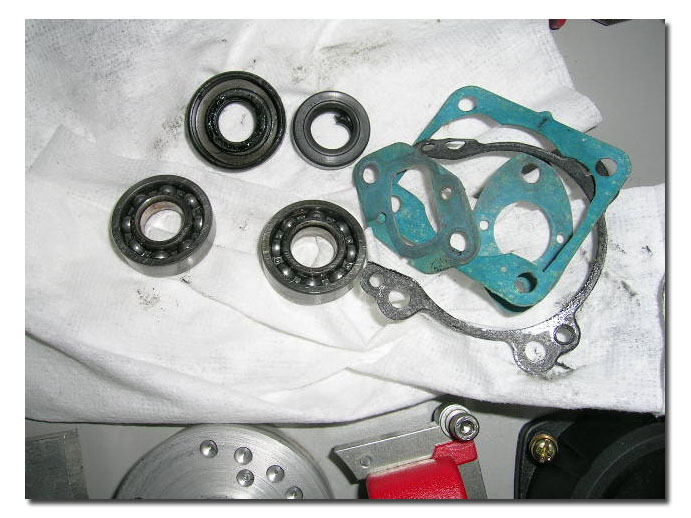
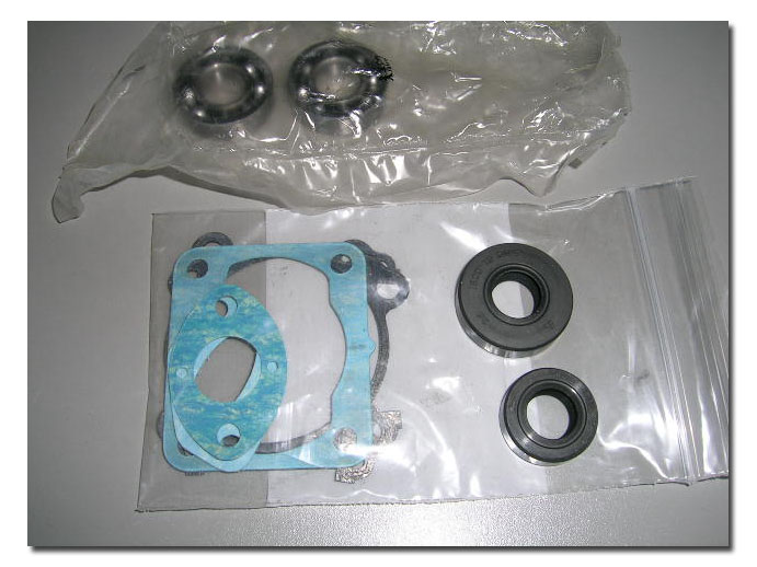
Pic 44: New replacement parts.
This pretty much covers the disassembly. Now for re-assembly!
Basically do everything in reverse order! I will cover most steps briefly and only point out important aspects! Most of the pictures are self explanatory, escpecially now that you know how everything came apart!
Pics 45 and 46: Installing the new bearings. If you removed the snap ring in the output side case, make sure to re-install it prior to installing the bearing. Setup your case halves on a fire proof surface, this time bearing side up. Heat the cases with the propane torch to expand the metal. Without using heat measuring tools, there is no way of determining the exact amount of heat and time required. There are heat indicating pencils availlable that will melt when rubbed on a hot surface when the surface gets hot enough. You can equally use infra red heat guns, or heat controlled ovens. There are a multitude of ways of doing this. I have an infra red heat sensor gun, but don't actually use it for this. To be totally honest, I usually heat the case for about the same time as it took to drop the bearing. This is far from scentific, but seems to work just about everytime! Do it however you feel is best for you. When the case is hot enough, drop the bearing in the case, keeping it very parallel to the case. If you do it right and the case is hot enough, it will drop right in. If it is crooked, it will stay stuck in the case. DO NOT bang it in. Flip the case over and tap it on the table and hope the bearing comes out. If it does not, let it all cool down and heat the case to drop the bearing out. Wait for everything to cool back down and start over. It may also be wise to check the bearing for free movement, and replace if required if this happens. This gets easier after doing it a few ( or many) times! Do not try to install a hot bearing into a case. You will have to heat the case too much to get enough expansion. Let the bearings cool completely prior to installation. After the bearings are installed, do not turn the cases over until they have sufficiently cooled or else the bearings might fall out and you will have to start over.
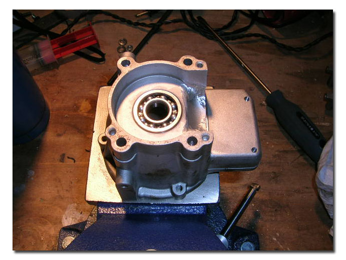
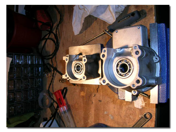
Pic 47: Cases with bearings installed. After the bearings are installed, the cases must be allowed to cool prior to oil seal installation.
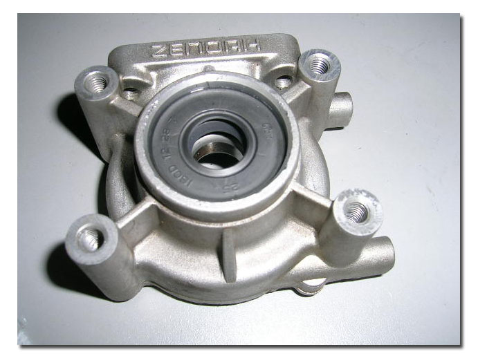
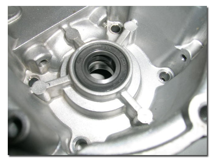
Pics 48 and 49: Installing the oil seals. Again there are different ways of doing this. I simply push in the seals by hand. Wetting them makes it a bit easier. Special care should be taken when installing the small oil seal since there is nothing to prevent it from butting up agains the bearing. This is not a good thing. I have seen premature wear to the seal because it was tight against the bearing. When installing this seal I push it in flush with the bevel inside the outer edge of the case. You will understand what I mean when you do it. The outer edge of the bore in the case for the seal has a bevelled edge. Push the seal in so it ends up just flush with this and it will not rub against the bearing, yet it will seat properly and not move or come out. Compare all around the edge to ensure the seal is in parallel with the edge. The large seal is less of a problem since the snap ring in place prevents the seals from going in far enough to touch the bearing.
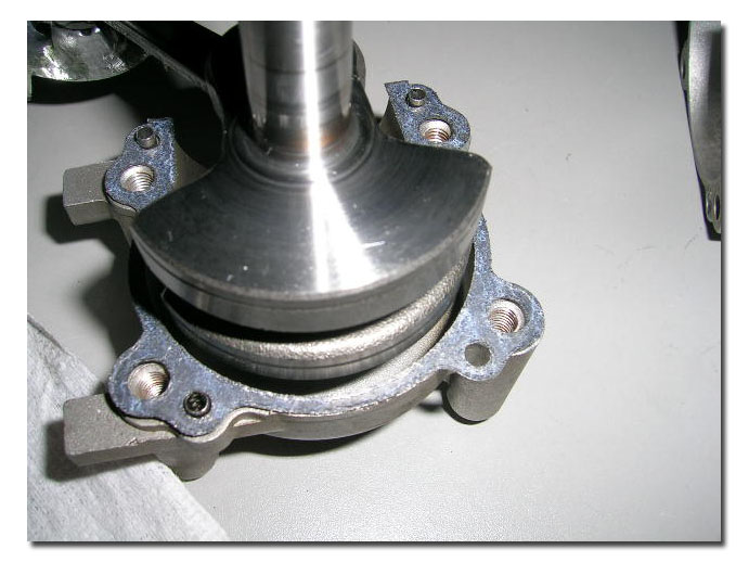
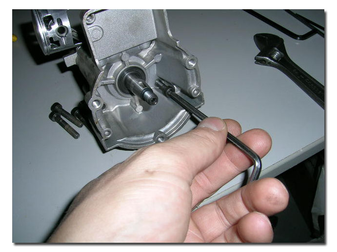
Pics 50 and 51: Install the crankshaft into the output end case half. Fit the new case gasket onto the case and locating pins. Fit the flywheel end case over the crankshaft, matching the two cases together. Make sure the gasket is properly in place. Install and tighten the four allan bolts that hold the cases together. Torque these in a cross pattern to allow for proper seating.
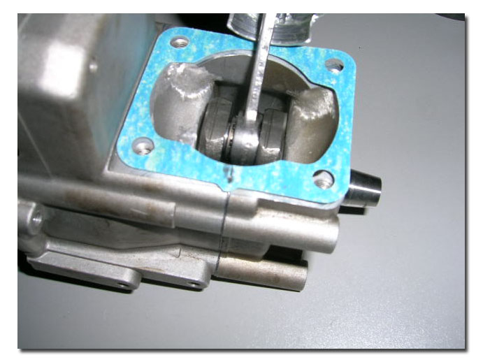
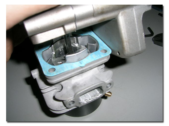
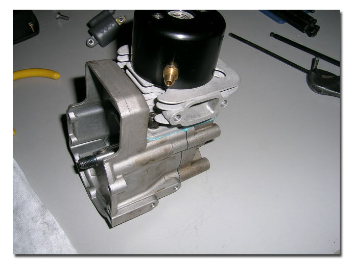
Pics 52, 53 and 54: Install a new cylinder gasket and fit cylinder on crankcase. (I am assuming here that the piston and ring are installed since they weren't removed in my example). If you did remove the piston and ring, you must install them as follows. Install the needle bearing in the connecting rod. Install both spacer washers (either side of needle bearing). Fit piston over the connecting rod taking care not to let the washer/spacers fall out. Install the piston wristpin and snap rings to secure the wristpin in the piston. These are a little tricky to install and can sometimes be a real pain, but I have found no magic method, so live and learn! :) Some good advice here: never install old snap rings! They cost next to nothing and pretty much will destroy your motor if they come loose in operation. Also make sure you have at least 2, preferably more on hand when doing a rebuild. They tend to sometimes pop out and disappear when installing them!
To fit the cylinder over the piston, here is my method. Drop the clinder gasket over the piston and let it lay on the base. Rotate the crankshaft to get the piston as high up as possible (TDC) and hold it with one hand while compressing the ring. Make sure the ring ends close together at the locating pin, which by the way should be on the intake side of the motor when you re-install the piston! Hold the cylinder with your other hand, ports located correctly in reference to the base. Slip the cylinder gently over the piston and ring. It should go in smoothly. If it doesn't do not force anything, try again, making sure things are properly aligned. The base of the cylinder "sleeve" is tapered to allow for an easy fit of the ring, which will completely compress once in the cylinder properly. Just make sure the alignment is as it would be once bolted together and the ring will not snag anywhere when pushing it in. I Then flip everything over, position the gasket on the cylinder and ease everything together. This avoid pinching the gasket in most cases.
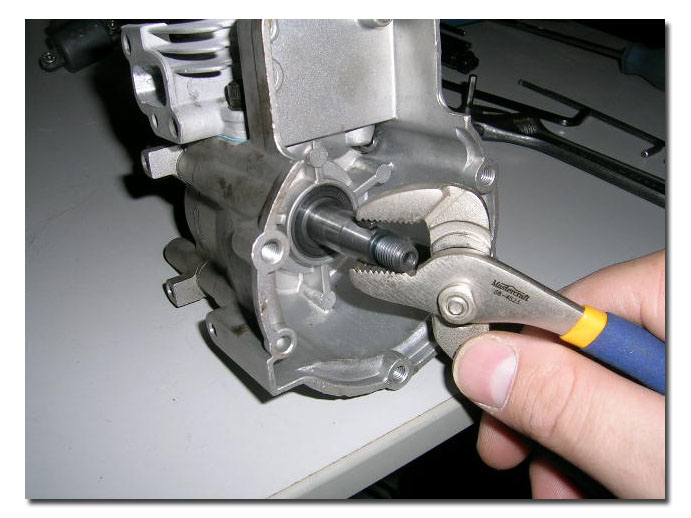
Pics 55 and 56: Installing the key in the keyway. I use small chanel-lock pliers for this...make sure it is properly positionned and seated otherwise the flywheel might not seat properly.
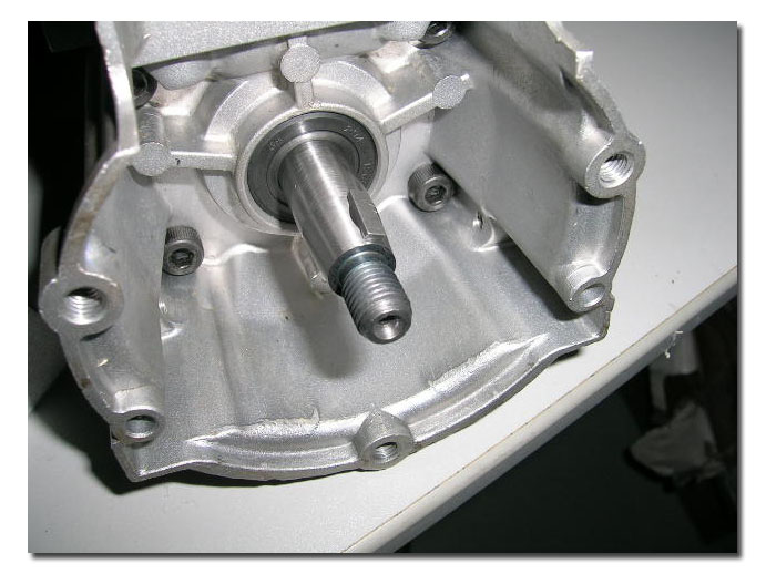
Pics 57 and 58: re-installing the pulley. Carefully fit the flywheel on the crankshaft, making sure to align the key properly. I use the same 6mm allan bolt used to lock the flywheel as used when removing the pulley. This time it's positionned at 5 Oclock. It will hold the flywheel while you tighten the pulley. Tighten the pulley firmly. Don't forget to remove the 6mm bolt after!
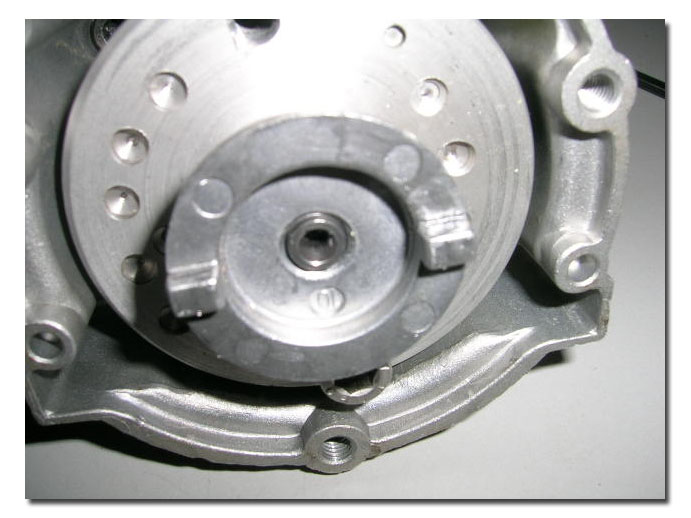
Pics 59 and 60: Install the pickup coil. A standard business card works well for setting the gap if you don't have feeler gages. Slip the business card between the flywheel and the coil. Rotate the flywheel so that the magnets align with the coil. They will pull the coil very tightly against the card. Secure the bolts.
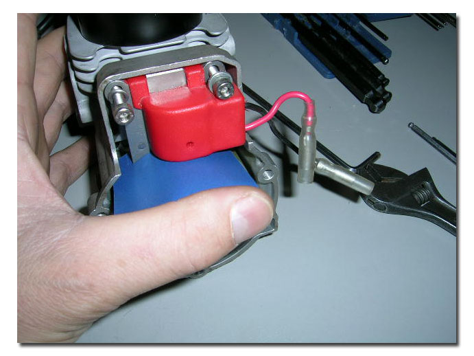
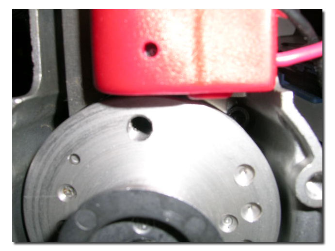
Pics 61 and 62: Install backplate and pull starter.
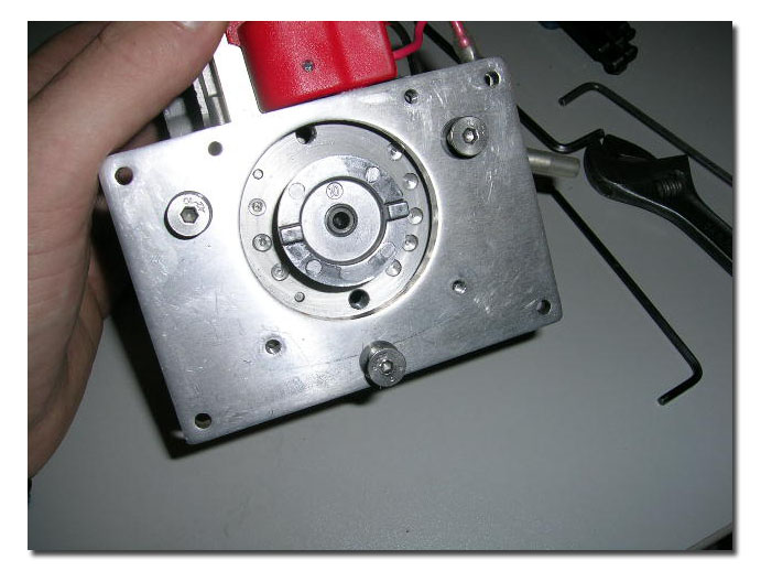
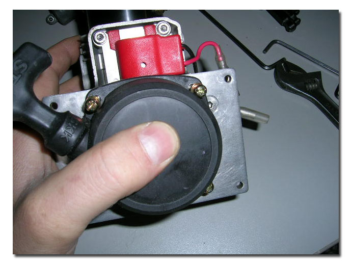
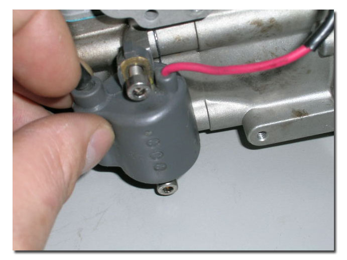
Pics 63 and 64: Install the grey coil and plug it back into the pickup (red) coil.
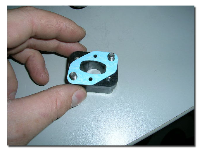
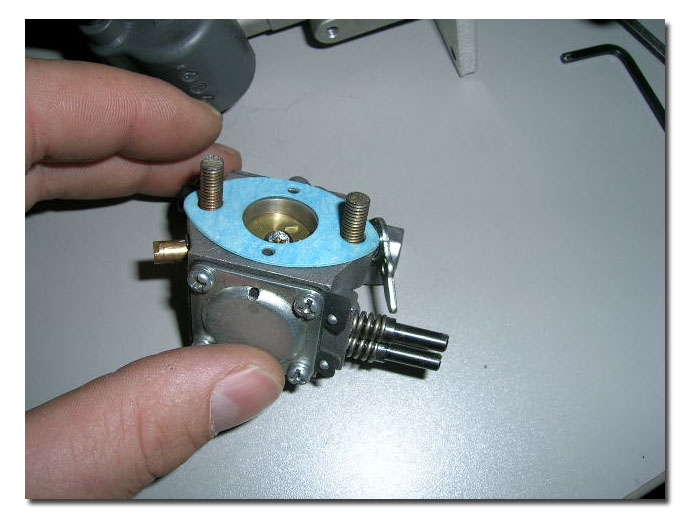
Pics 65, 66 and 67: Mount the carb spacer and gasket to the cylinder. Mount the carburetor and its gasket to the carb spacer. Do not overtighten when mounting these parts, the carb spacer can easilly be distorted if overtightened, and this will cause a primary air leak that will lead to obvious problems when trying to tune the engine.
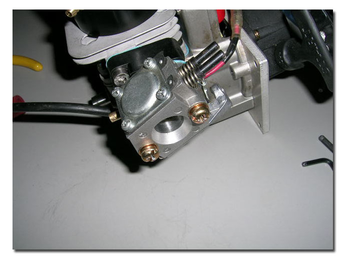
Pic 68: Engine completely re-assembled. Only the spark plug is missing now.
That's it! We're done!
I hope this information can help hobbyists that are comfortable doing so, work on their motors. If you are not comfortable attempting this, there are many reputable builders out there that can do the job for you.
Happy Boating!
For all the torque specifications for Zenoah Engines as well as maintenance specs click HERE :

