
Read all about what makes a stock Zenoah into an Outlaw modified Zenoah!
***This article is reprinted from the September 2008 NAMBA Propwash with permission from the author and NAMBA. The entire newsletter can be found at www.namba.com.
We have been developing Zenoahs for several years. There are three classes of Zenoahs in NAMBA, “stock” for the Thunder boat class, mildly modified for the G1 class, and “outlaw” for the GX1 class. My designation of the M&D cast cylinder engine as “outlaw” comes from the IMPBA outlawing the cylinder that was specifically designed to fit the LS27 class. There are more powerful GX1 engines, and I believe a 10 horsepower custom built 26cc engine should be possible. We consider the M&D double cone pipe to be the standard Zenoah pipe. There are pipes that improve specific areas on the power curve, but the double cone pipe is a good compromise and gives a G1 engine a broad power curve that is easy to prop for.
For comparison, here are the port timings and other details from the test engines:
| Stock Zenoah | Miller Zenoah | M&D Cast Cylinder | |
| Exhaust | 164 deg duration | 188 deg duration | 184 deg duration |
| Transfer | 124 deg duration | 126 deg duration | 122 deg duration |
| Intake | 146 deg duration | 158 deg duration | 166 deg duration |
| Squish Clearance | .032 |
.010 | .010 |
| Combustion Chamber Volume |
2.4cc | 2.0cc | 2.0cc |
I need to explain a few things about our dynamometer. It is an inertial dynamometer; that is the engine accelerates a flywheel and the change in speed of the flywheel over time is a measure of the engine’s torque.
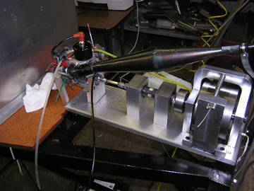 Unlike brake dynos that measure power under steady state conditions, inertial dynos measure power in a rapidly accelerating engine. This is similar to the way racing engines work. The inertial dyno also allows very rapid testing. We often make 50 individual runs in an afternoon. We have not carefully calibrated our dyno so its results may not match other dynos. I know that a particular engine tested both on our dyno and a similar dyno shows nearly ½ horsepower less on our dyno. Power measured on the same engine will vary from day to day even with corrections for atmospheric conditions. We try to compare changes on adjacent runs with a calibration check run at the end that duplicates the starting conditions. All the curves in this article are the average of at least two runs. Even so, there is irregularity in the horsepower curve from noise in the rpm measuring circuit. Another series of tests on the CMB 35 can be found at www.modelgasboats.com. A complete description of the dyno with design and building instructions is in issue 14 of Model Engine Builder.
The stock engine specified for the Thunderboats should guarantee level racing in the class. However, the pipe was left open. The Zenoah has a relatively restricted intake tract. This can be overcome either by raising the intake timing or by using a pipe with a strong suction pulse. We used an accurately machined pipe with an adjustable baffle cone to investigate possible power gains from a high suction pulse pipe. Below is a picture of the billet pipe along with the M&D pipe.
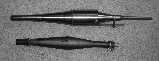
This pipe uses a three stage diffuser with a high horn coefficient and large diameter to expand the exhaust pulse more than most pipes. With the right tuned length, this will result in a low pressure at the exhaust port when the piston is around bottom dead center. We find that moving the diffuser section on the header doesn’t make much difference in the tuned length as long as the baffle cone is kept the same distance from the exhaust port. There is s best position for the diffuser section and it is the design position. We changed the tuned length of the pipe by moving the baffle cone, i.e. by changing the band section width. Below are the dyno graphs for these changes. Only a few of the many band changes are shown on the graph for clarity. The first number in the legend is the length in millimeters from the exhaust flange to the beginning of the band section and the second number is the band section width in millimeters.
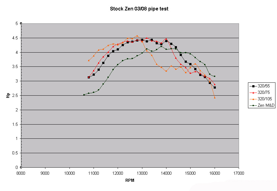
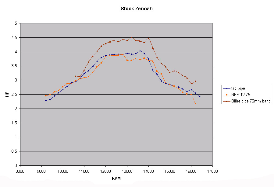
The lower curve is the power with the M&D double cone pipe. It is easy to see the power gain from the fat, wide band pipe. We decided that a 75 millimeter band width would be optimum for the good bottom end torque a heavy boat would need. Several months later we tested the billet pipe with a 75 millimeter band, a fabricated version of the billet pipe, and a commercial band pipe with a straight cone diffuser section. The commercial pipe is pictured below.
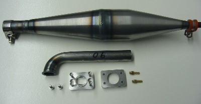
It is easy to see both the superiority of the three stage diffuser in the billet pipe and the power loss from inaccuracies between the billet and the fabricated pipe. Nearly ½ hp gain over commercially available pipes is possible from a custom pipe.
Some other small power gains are possible with plug and carb butterfly opening changes. I doubt that the rules really allow some of these changes. Breaking in the seals will also help. Removing the seal springs should be illegal, but would be hard to check. Changing the cylinder base gasket to a thinner one should be illegal but would also add power.
By far the most popular engine is the Zenoah with the modifications allowed under NAMBA’s G engine rules. Here, material can be removed to modify the engine. An excellent article on this by Scott Schneider can be found at www.modelgasengines.com. The modifications to the test engine are described and illustrated below.
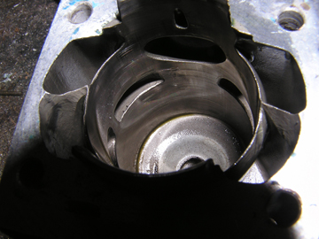
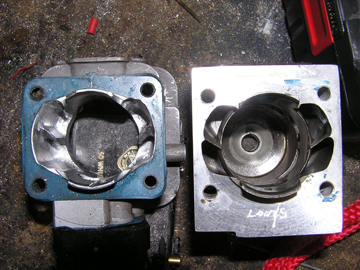
The first problem with the stock engine is excessive head clearance. This should be lowered to .010 to .015 inch by machining the cylinder base. The top 3/16 of the piston should be machined around .004 of an inch smaller in diameter to eliminate piston seizures. I also machined a flat top on the piston and removed a lot of material from the inside to reduce piston weight. It is possible to machine the squish area both in the head and on the piston to match the angle. Though this was done on this engine, I’m not sure it made a power difference compared to previous engines. Finally, the skirt of the piston was slotted to improve transfer flow.
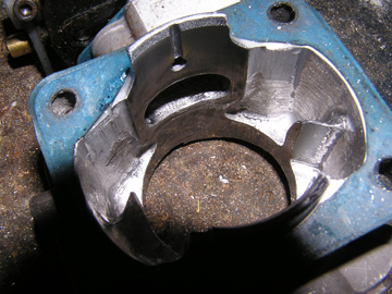
The transfer ports were raised by the same amount machined off the cylinder base. The rear transfer was seriously widened as well. The exhaust port was widened and raised. Thirty thousandths of an inch was machined off the intake side of the piston skirt to raise the intake timing. Because both the amount machined off the cylinder base and that machined off the skirt affects the intake timing, .010 less was machined off the piston skirt in this engine because .010 more had to be machined off the cylinder base. This was needed to get .010 inch squish clearance due to the amount machined off the top of the piston and the combustion chamber. Below are tests with this engine using two different pipes.
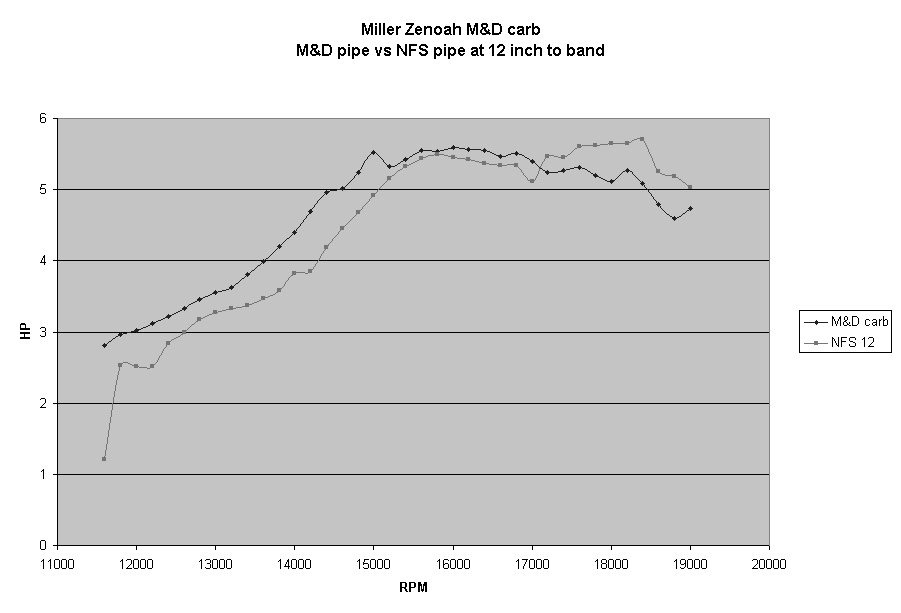
Notice that there now is less difference between the band pipe and the double cone pipe. This is a contrast to the graph for the stock Zenoah where the band pipe was clearly superior. Because we have raised the intake timing, opened up the transfers, and raised the exhaust, there is much less restriction through the porting, and the lack of a strong suction pulse is not as important.
The other area for improvement is the carburetor. We have a flow bench setup to test Walboro carbs on a cylinder. These tests show that things in the bore are much more important than the bore diameter.All stock Walboro carbs have the same .500 inch venturi bore unless noted. Below is the flow at 13 inches of water:
| Modified WYK | 81 cfm (.610 bore, barrel style carb) |
| M&D modified WT-257 | 65.5 cfm |
| Miller modified WT-257 | 63 cfm |
| WT-257 | 61.8 cfm |
| WT-287 | 58 cfm |
| WT-813 | 56 cfm |
| WT-745 | 55 cfm |
| WT-644 | 53 cfm (Modified WT-644 61 cfm) |
| WT-EX520 | 48 cfm |
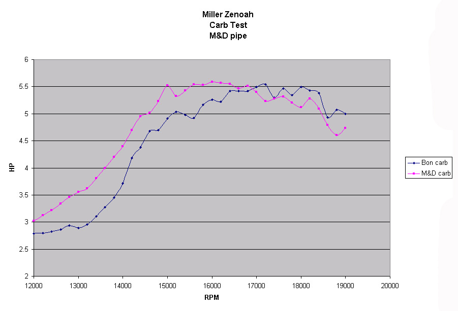
A good comparison is an M&D prepared carb to a Bontoft carb. Though the bore of the M&D carb is larger, its butterfly is only slightly thinned on the leading edge. The Bontoft carb has the shaft cut down, the butterfly streamlined, and the stop cut so the butterfly opens a little past the normal position. The difference in power is shown on the graph below. Even more top end power is possible with a shorter carb isolator block that tunes the intake tract for a higher rpm.
The ultimate Zenoah is one where the standard die cast cylinder is replaced with an investment cast cylinder available from M&D Designs. This cylinder incorporates all the modifications mentioned above as well as better transfer port shapes. The inner wall on the transfers helps improve the flow as well as providing better piston support. The carb is raised up the cylinder to improve the intake timing, and the exhaust port is raised and angled down. The only modification needed to the rest of the stock Zenoah is to lighten, relieve, slot, and flat top the piston. M&D also installs their low drag seals. The clear superiority of the engine can be seen in the graph below. he stock engine was tested with the billet pipe and stock carb. The others were tested with the M&D carb and M&D pipe.
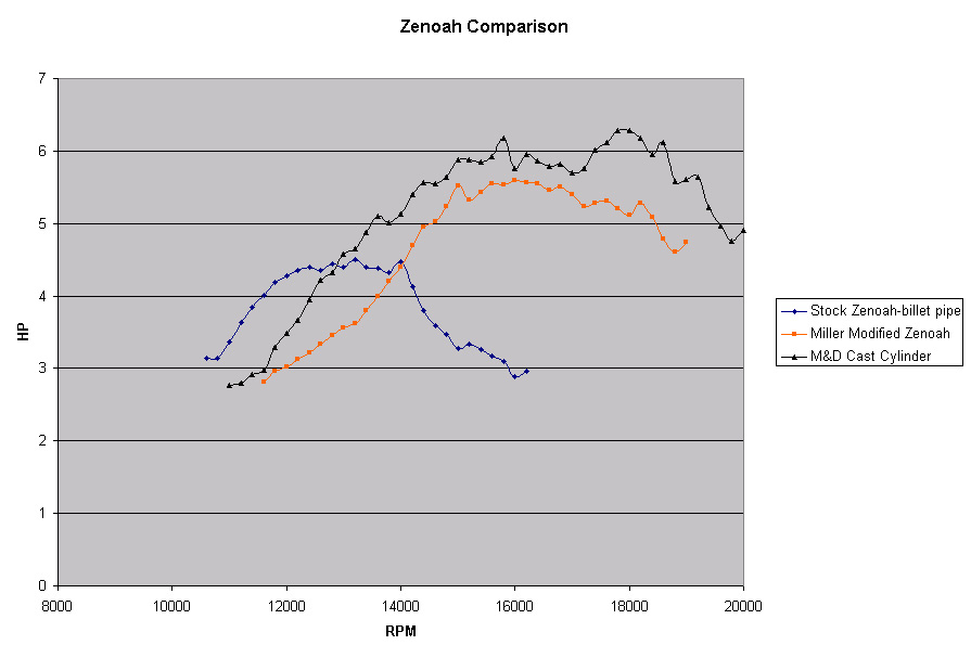
So what does all this mean in your boat? The speed of a boat increases approximately as the power cubed. That is, if you double the power the speed will only increase by about 1.26 times. That is why it is hard to test engine power by observing boat speed. If your hull goes 55 mph with the stock engine it would go about 59 mph with the modified engine and 61 mph with the cast cylinder engine. The two mph difference between the modified and cast cylinder engine explains why G1 engines are very competitive in the GX1 class. Lots of other factors will overcome this small edge in speed. In a stock engine class, if your boat goes 55 mph with a double cone pipe, it would go 56 mph with the billet pipe. Again, many other factors will negate this small speed difference. The best engines will have a broad, flat, peak power band. This gives an engine that will handle a broad range of props with good power both in the turn and at the end of the straight. If everything else is optimum, the most powerful engine will give the winning edge.

