Tech Article ...
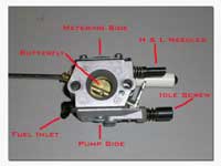
Get to know your Walbro carburetor better...
Click here for the German translation of this article!
Klicken Sie hier fuer die deutsche Uebersetzung dieses Artikels!
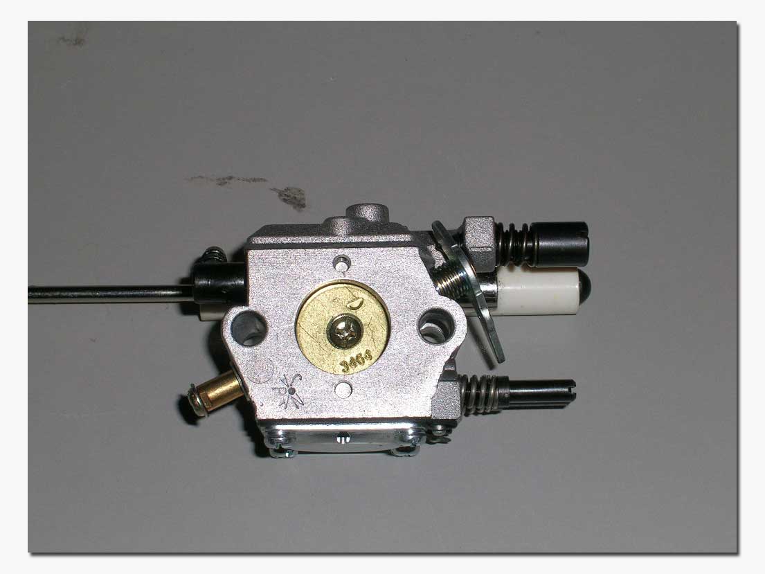 At the heart of
just about every Gas boat power plant is a Walbro diaphragm carburetor. Although there are several different models
being used, the basic construction and function are the same or quite similar.
Keeping the carburetor clean and well maintained is probably one of the single
most important things to assure a great running engine. There is no real
mystery to properly maintaining your carburetors. Simply use good work
practices; keep work area clean, be careful and take your time.
The stock Zenoah marine engines usually come with a Walbro 644 carburetor which incorporates a choke and primer bulb. This is a good carburetor and well suited to the stock engine. It does however require the use of a polymer "spit tube" which is included with the new engines. Since the 644 does not have a bell-shaped intake bore, if it is used without the included spit tube, most will notice problems maintaining accurate needle settings from one outing to the next. If the stock carburetor will fit in your boat using the spit tube, by all means use it...it will work fine for most applications.
On modified engines however, the Walbro 257 has pretty much become the standard carburetor to use. For this reason, I will show the 257 in this article. Performing the maintenance on the 644 or even a 167 or other Walbro carburetors would be quite similar if not identical in some cases.
 The
first thing you will want to do, no matter which carburetor you are using, is
to take out the Idle Screw and spring and chuck them! This is not needed in an R/C application.
Most sanctioning bodies require that the boat have the
 possibility to be shut
down by radio, so the butterfly must be free to travel to the closed position
when the driver backs the throttle far enough on the transmitter. In other
words, remove the idle screw and set the throttling range of your radio gear to
go from fully closed to fully opened and you're all set.
A little bit of theory...
Probably the most important thing to grasp when it comes to carburetion with our small 2-stroke engines is that the air not sucked into the cylinder, but rather pushed in by atmospheric pressure. At a certain point during the engine's cycle, there will be a vacuum created in the crank case. The difference in pressure between this vacuum and the atmospheric pressure outside the engine is the "push" that will cause air to enter the engine through the carburetor. The more air is pushed into the engine, the denser it becomes and the more power is produced. At sea level, atmospheric pressure is about 14.7psi. As you increase in elevation, this pressure reduces, thus the natural "push" of air into the engine is reduced. Typically this equates to approximately 3.5% power loss for each 1000 feet elevation. Air temperature is also a factor, as colder air is denser than warm air, at colder temperatures, for the same elevation, an engine would produce more power.
Rich or Lean...
As with any type of fuel, gasoline must be combined with air to burn. The stoichiometric or "perfect" mixture for gasoline is 14.6 lbs of air per pound of gasoline. At this ratio, you would get the perfect burn of a charge and thus the most power and least emissions. This is however a theoretical value that is not practical for our power plants.
Rich: Typically, a richer setting must be used in order for our small engines to survive. A richer setting means that there is more fuel in the mixture entering the engine, which is called "excess fuel" in combustion terms, and serves as coolant for internal engine components. The target setting for maximum performance is: just rich enough to keep cool.
Lean: Obviously, the opposite of the rich setting is the lean setting. In this case, the needles are closed to a point that there is too much air and not enough fuel entering the engine. This will cause a lack of cooling of the internal components of the engine, and eventually seizure. Too lean a mixture can also cause detonation (an uneven burning of the fuel inside the cylinder) which puts extreme loads on engine components and causes them to fail.
Now on to the maintenance of our carburetor...

If your carburetor is dirty, you will want to clean it up before starting to disassemble it. Compressed air and denatured alcohol or carburetor cleaner will come in handy for cleaning part of the carburetor. When I refer to using compressed air in this article, please keep in mind that this is to be done using common sense. Do not blow directly into openings with 120psi air. This kind of pressure simply isn't required here.
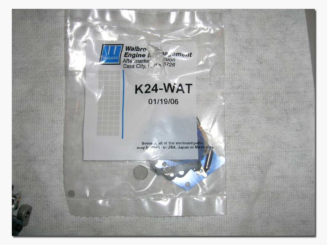 ***
Also, very important: if you are going
to perform maintenance on your carburetor, please have a repair kit on
hand. Even though you might be able to
put the carb back together with the old parts, there is also the chance that
you tear a gasket or diaphragm, etc. In
most cases if you are opening the carb to perform a maintenance it is probably
because you noticed a reduction in performance, so why not be ready to rebuild
the carb and do it properly! Kit in picture is an
example only.
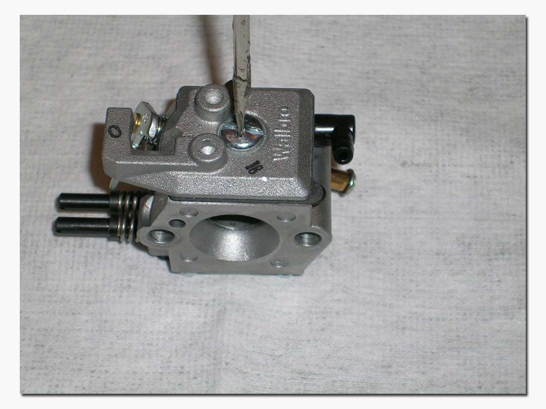 We will
start by opening the pump side of the carburetor. This is the side with the
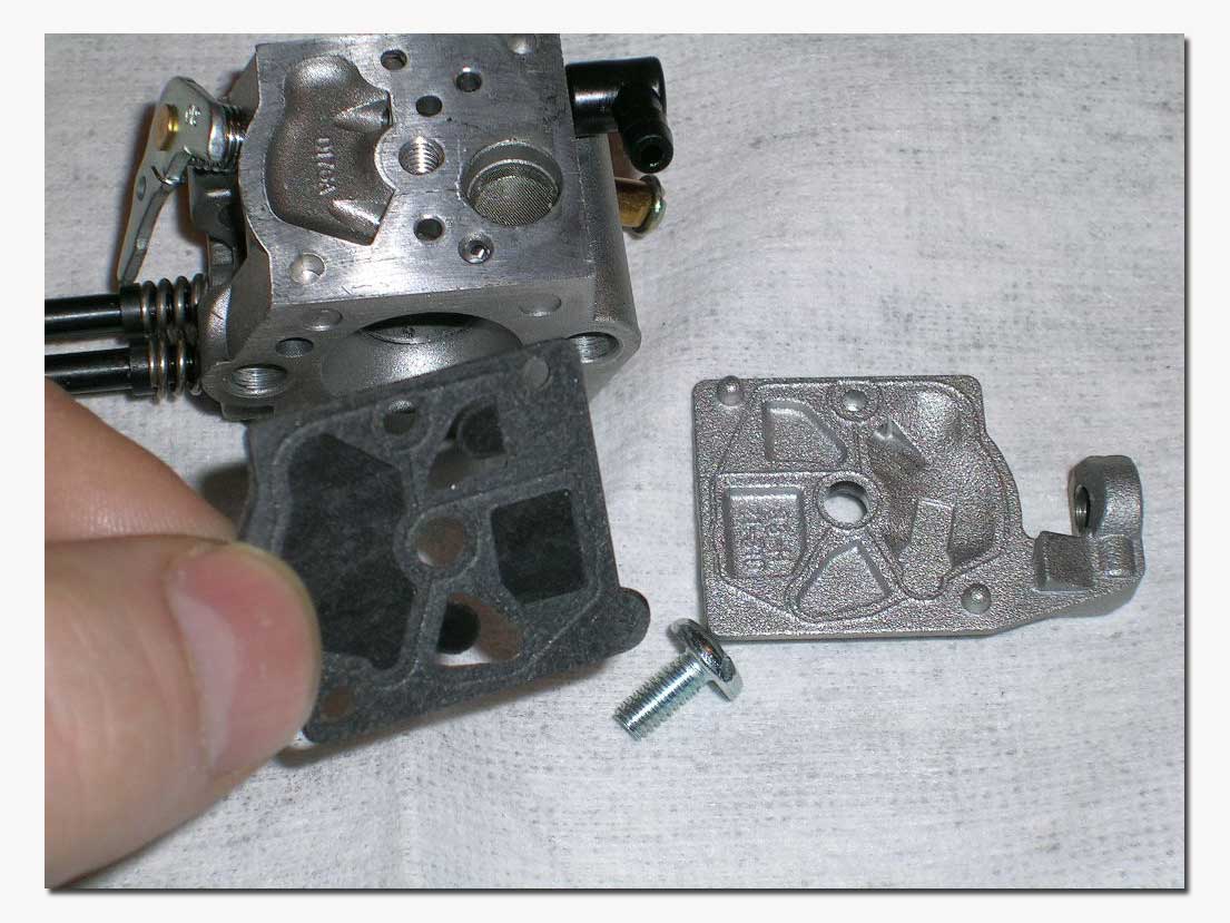
single screw plate cover. Remove the screw and the cover. Underneath lie a
sealing gasket and the pump. These two
pieces usually will stay together as one when you remove them. In a new kit
they will be separated. You want to make sure they are clean and free of any
debris. Also very important is that the two "flaps" must lay perfectly flat on
the carburetor body as these are actually the pump's check valves. If these parts seem in any way worn or
deformed, they should be replaced. Clean
the carb body with alcohol and compressed air.

With the pump and gasket removed you will have access to the fuel inlet filter. You can remove it using a small pick or screwdriver. This filter can be cleaned with compressed air and/or alcohol. Many boaters prefer to simply have many new ones handy and replace them frequently. Others simply remove the filter completely, although this might not be ideal for most. Personally I remove the filter and use a good inline fuel filter on the fuel line just prior to entering the carburetor. It is much easier to service a dirty external filter than to have to open the carburetor to service the internal filter! This is of course a matter of personal preference only.
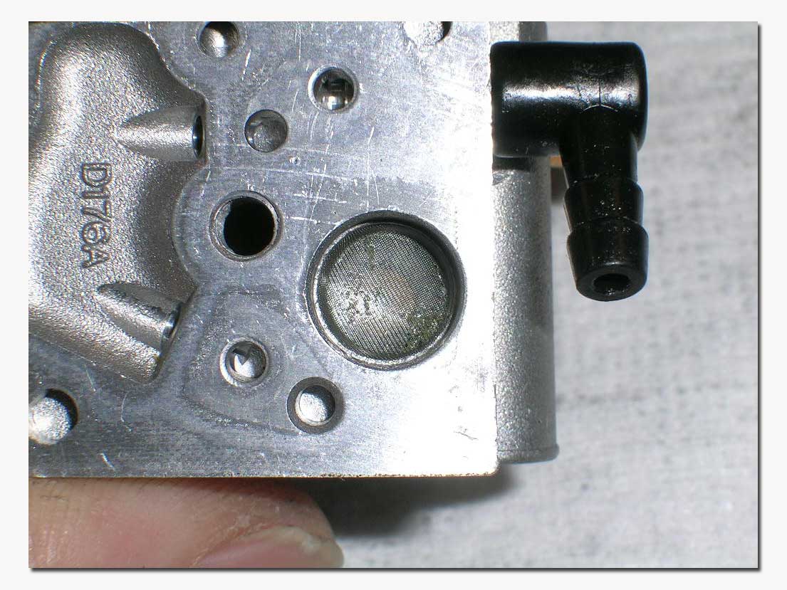
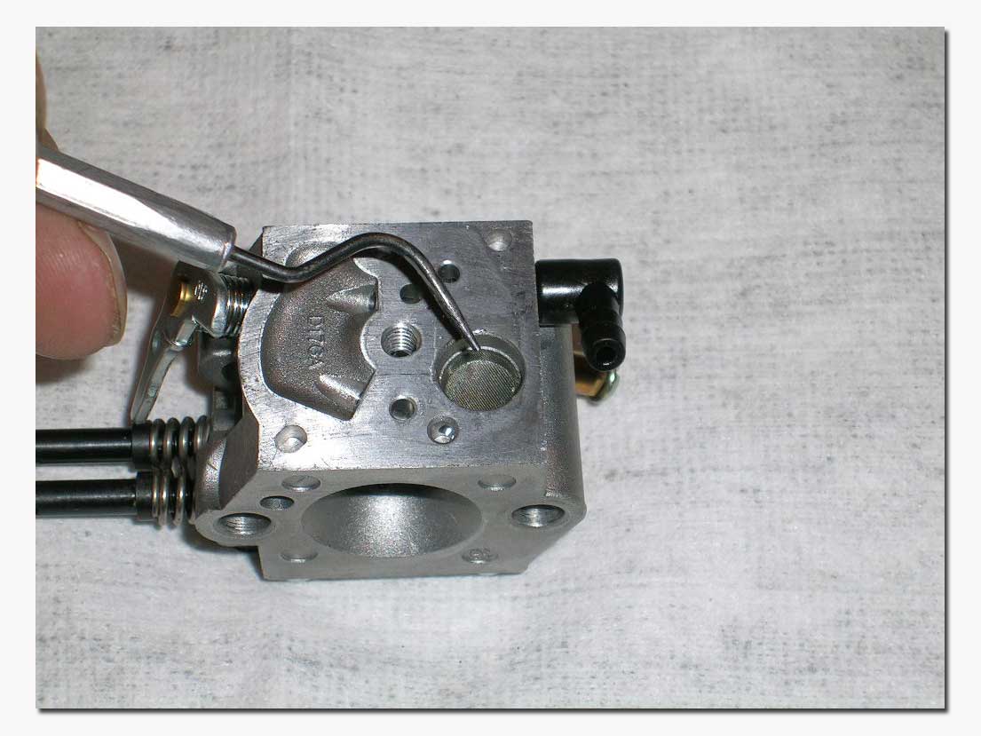
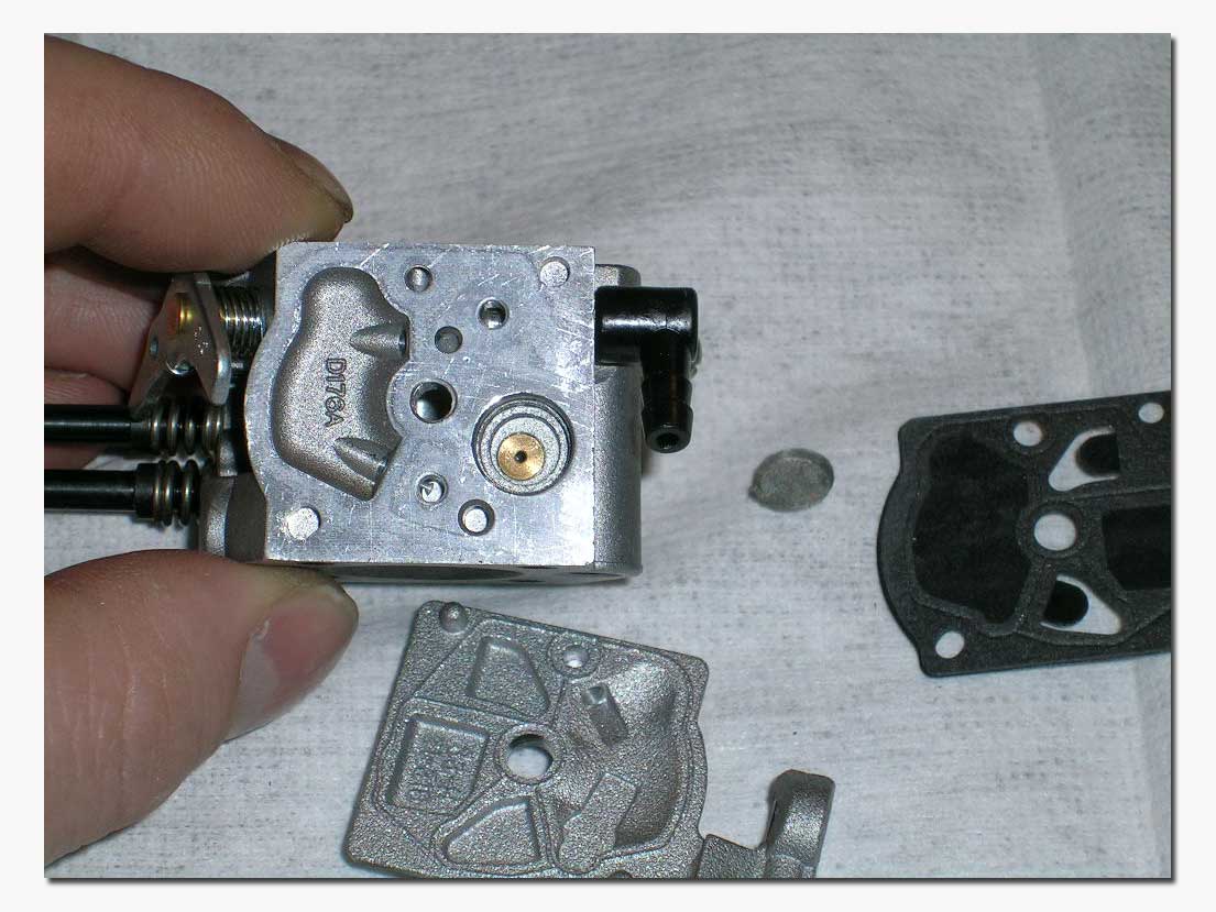
Here you can see that the filter in this carburetor is a little dirty. In the picture below you see the carburetor body with the screen filter removed. Again, clean everything. Inspect the inside of the cover. You will notice a "crush rib" along the edge of the cover. This is for good sealing of the pump and should not be damaged.
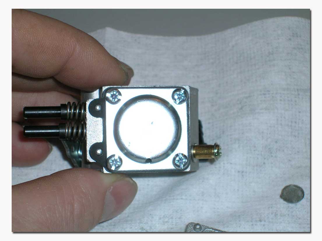
Now for the fuel metering side of the carburetor....On this side there will be a plate held down with four screws. It might be a blank plate as pictured here, or it could also have a primer bulb as pictured further down. Make sure the vent hole in the plate is not obstructed as this allows atmospheric (reference) pressure on the top of the metering diaphragm. Removing this cover will allow access to the metering diaphragm and gasket. Remove carefully.
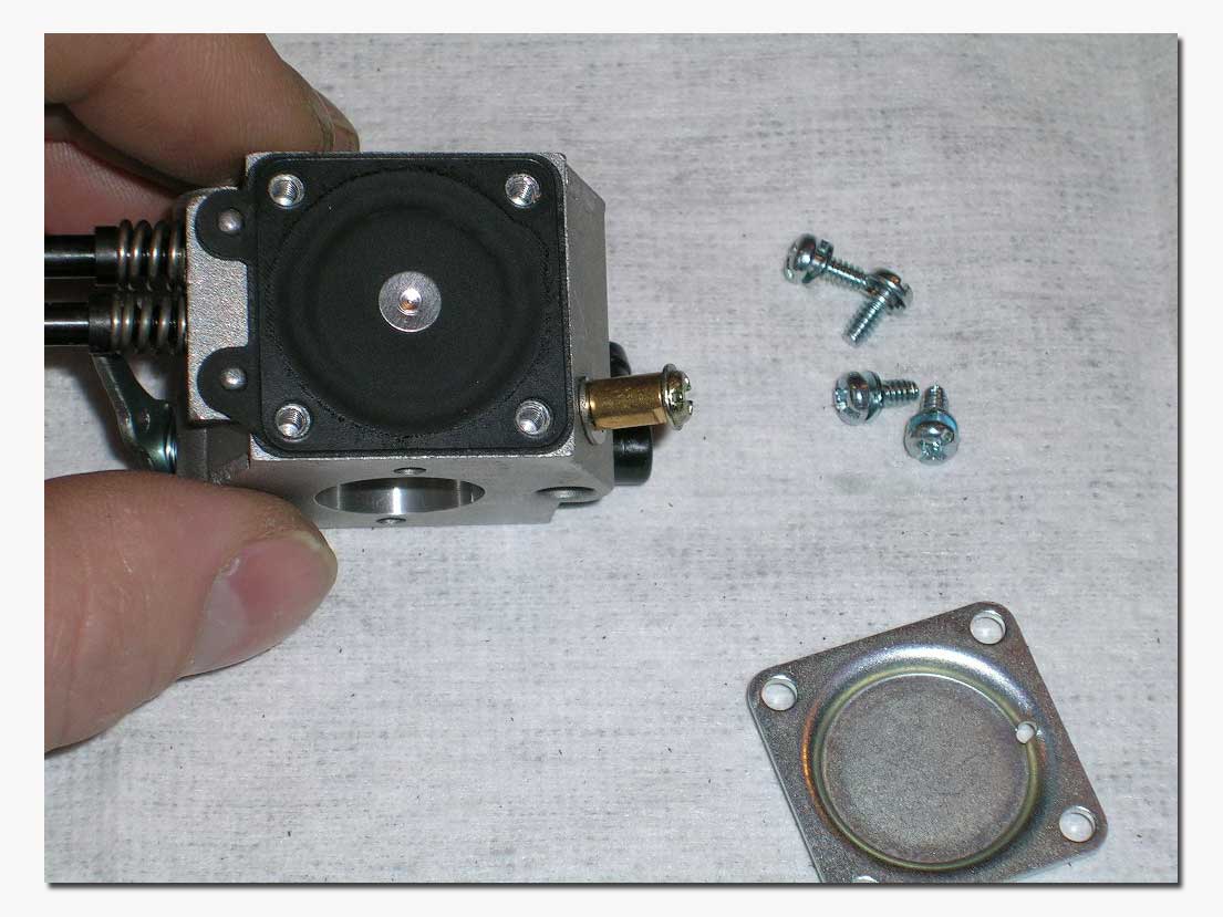
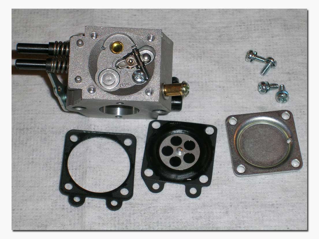
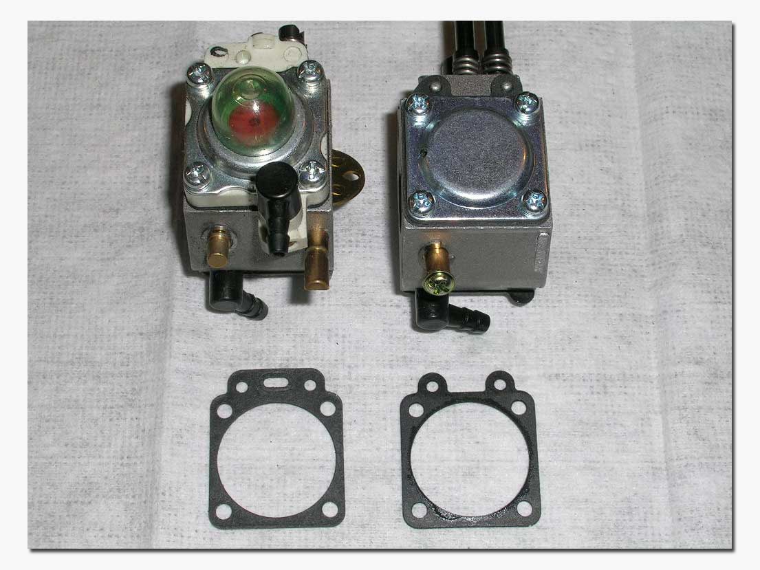
The diaphragm and gasket should be inspected for signs of wear or deforming. It is hard to explain what to look for as far as wear goes for the diaphragm, but if it is stretched out too much this will affect the carburetor's performance. The best way to check this that I have found is to have a new one to compare to. If the old one seems to be stretched much more than a new one, replace it. Pictured below are a 257 carb (on the right) and a 644 carb with a primer bulb (on the left). Notice the different type of sealing gasket. The gasket from a 644 will work on a 257 carb, but the opposite will NOT.
The metal backing plate on the metering diaphragm has a little stub shaft that pushes on the metering arm of the needle valve. This assembly "meters" or regulates the amount of gas into the carburetor and is a vital part of the carburetor. The needle valve assembly is comprised of a needle, metering arm, spring and pivot pin. To remove the assembly for inspection, simply remove the screw holding the pivot pin in place. Be careful when removing these parts as the small spring can "pop" out. It is important to note here that all springs are NOT the same for Walbro carburetors, and that they should not be mixed and matched unless you really know what you are doing and have the correct tools to perform "pop-off " and "re-seat" pressure tests (not covered in this article). For this reason it is important to be certain that you have the correct rebuild kit for your particular carburetor if you are replacing parts. Again, clean everything thoroughly. The tip of the needle is made of soft rubber and should be inspected for signs of wear or deformation. Replace if necessary. You can use a cotton swab and cleaner to clean the inlet seat (chamber that the needle sits in).


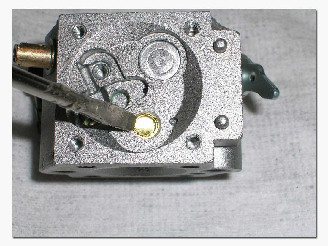
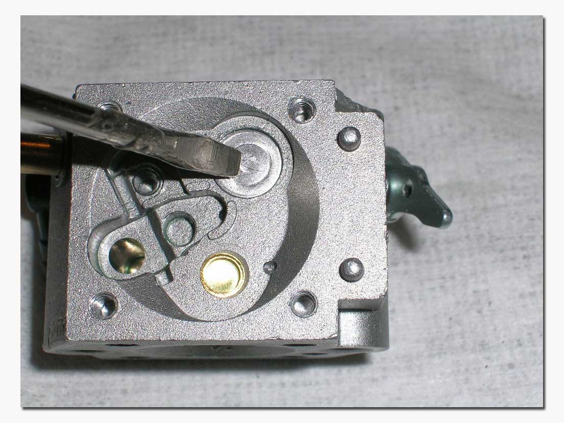
 The
gold plug seen in the above pictures is a "cup plug". Underneath it is a tiny
screen, called a capillary screen. This is the capillary check valve system
used on the 257 carburetor. Removing the cup plug can be accomplished by using
a #8 bottoming tap or an 8-32 screw works fine also. Screw the tap into the
plug, then pull the plug straight out. If you remove the cup plug, you will see a
little circlip holding the screen in place. Removing this circlip will allow
you to take out the screen and clean the main nozzle passage. These parts do
come with some of the rebuild kits, but unless everything else fails, I recommend
that this be left alone, as it is very easy to mess something up here! If you
look closely at the picture, you can see a small hole just at 3 O'clock of the cup plug in the lower left picture. If you want to blow out
the main nozzle passage without disassembling the cup plug, you can use a short
piece of silicone tubing and press it firmly against this hole and blow into
the other end. You should hear the air coming out in the carburetor throat at
the main nozzle. * I would not recommend using compressed air for this, as the
capillary screen could be damaged. * In the picture below you can see where
this passage goes into the well under the cup plug.
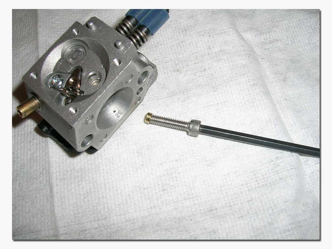


If you do decide to remove the cup plug to clean or replace the capillary screen, make sure when you re-install the new cup plug that you do not push it in too far, as this could block off the fuel passage to the main nozzle. Make sure to observe the position of the cup plug BEFORE you remove it so that you know how far to push the new one in.
 The
silver color plug seen in the pictures is the "welch plug". Underneath the welch plug are the idle
passages. (Seen in this picture on the left) This plug is removed by either
using the Walbro 500-16 tool or a very sharp small flat screwdriver. The tool
must be held at a shallow angle to the plug and driven through it VERY
carefully. Then you pry the plug out. If the tool is not held at a shallow
angle, the passages underneath it can be damaged. To clean the passages use
some cleaner and low pressure air. Seen
below are the three "transition holes" in the carburetor throat (picture on the
right). These are part of the idle circuit that feeds fuel to the engine at
starting and low speed. In the picture on the left you can see the main nozzle
in the venturi of the carburetor. It's the small hole at the top.


A little bit more theory...
This time about what's going on in the carburetor throat...
As the engine is started...Assuming the carburetor is being choked. At this point, cranking the engine creates a vacuum in the crank case causing the same vacuum in the carburetor throat. There is very little air flow in the carburetor and an unusually high amount of gasoline is being drawn into the air stream through the main nozzle and transition holes.
At idle...As the engine starts running, the choke is opened and the engine idles. At idle the butterfly or plate is nearly closed. In this position there is one transition hole on the engine side of the butterfly and two on the other side. There is a low pressure on the engine side of the butterfly and high (atmospheric) pressure on the other side of the butterfly. The high pressure enters the main nozzle and the two remaining transition holes and mixes with the fuel in the idle pocket of the carburetor. The fuel mixture is drawn out of the idle pocket into the low pressure (engine side) of the butterfly through the transition hole on that side. As this fuel is drawn out of the carburetor's idle pocket, this creates a low pressure in the metering system. Atmospheric pressure is applied to the metering diaphragm through the vent hole in the plate cover. The diaphragm in turn presses down on the metering lever releasing the spring pressure on the inlet needle allowing fuel to re-enter the metering chamber. Note: no fuel is being drawn from the main nozzle at this point.
At part throttle the butterfly is opened more and there is more air flow through the carburetor throat. There is still slightly lower pressure on the engine side of the butterfly and the three transition holes are now in that low pressure zone. Fuel is now being drawn into the air flow by all three transition holes. The metering system continues to refill the fuel chamber as noted in the previous step. At this point, because of the increased air flow in the carburetor throat, the venturi effect is starting to take effect. The venturi is the part in the carburetor where the throat comes to its smallest diameter before getting bigger again. As the air flow is forced to flow through this reduced diameter area, a low pressure is caused at that point because of the increased velocity. The main nozzle is located at this low pressure point of the throat. Because the venturi effect is starting to manifest itself, the main nozzle is slow starting to contribute fuel to the mixture.
At full throttle, as the butterfly is opened more it has little to no effect on the location of the high and low pressure zones within the carburetor throat. Since air is rushing in so fast, there is little to no vacuum created in the carburetor by the vacuum in the engine crank case. The only area in the carburetor now that has a vacuum is at the venturi due to the higher air flow. For this reason, at this point the main nozzle is the primary source feeding fuel for the mixture.
Moving on...
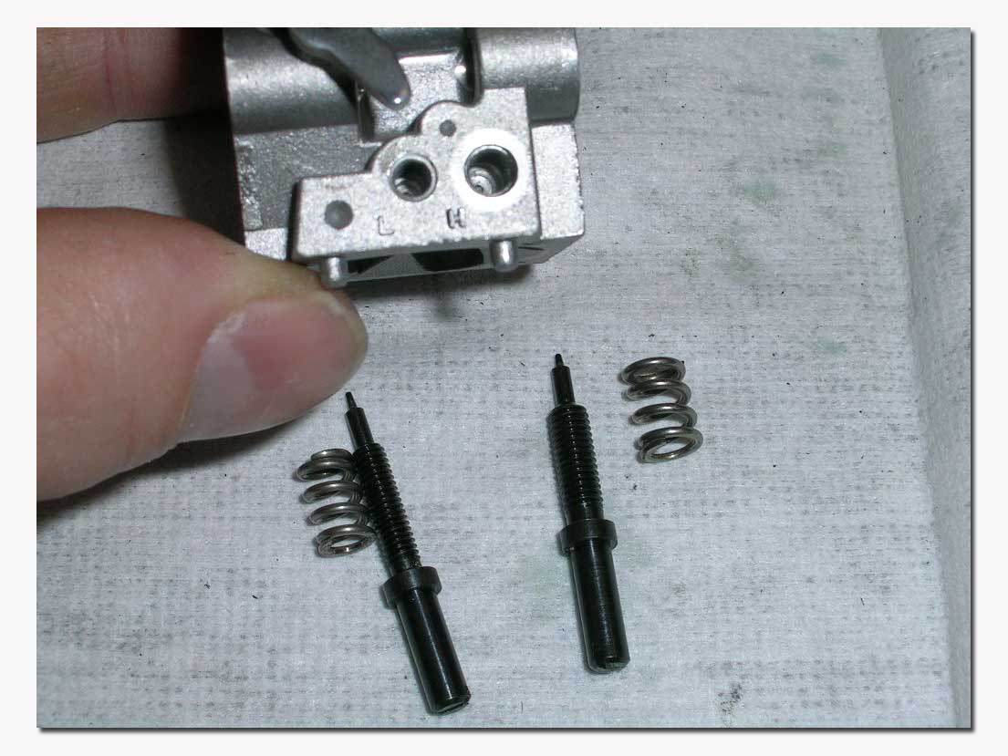
The low and high speed needles should also be removed and checked for wear. The wells can be cleaned with cleaner and air. Inspect the tip of the needles for grooves. A groove you can see is ok, but you should not be able to feel it with your finger nail. If you can, the needle and seat are mostly likely damaged and can result in very sensitive needles (hard to adjust properly). Damage to the needles and seats is the result of over tightening. When you close the needles to adjust you should bottom them out only lightly and never tightly to avoid damage. The needles can be replaced, but the seats can not and if the seats are too damaged, the carburetor is ruined.
Note: the high and low speed needles are of different thread sizes, so it is impossible to mix them up when re-installing unless excessive force is used.

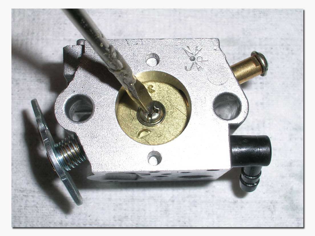
Another thing I like to do is check the screw that holds the butterfly on its shaft. If this screw ever comes undone while running full throttle (this has been known to happen on some carburetors) you will most likely be rebuilding an engine. As can be seen in the picture below, the tip of the screw is punched to prevent it from being unscrewed. In most cases this works well but I check it to make sure it's holding. On some carburetors that I found the screw to be easily unscrewed, I took it off and put high strength thread locker on it before re-installing it and punching the tip.

Reassembly...
Once you are sure everything has been thoroughly cleaned and inspected you can start reassembling in the reverse order that you disassembled everything.
To reinstall the welch plug, use Walbro 500-15 tool or equivalent. Lay the welch plug in place, apply some nail polish around its edge and drive it flat with the tool. Wipe off excess nail polish. It is important that the plug be flat so that it doesn't interfere with the metering diaphragm.
When reinstalling the cup plug, make sure not to push it in too far, or it could restrict the flow of fuel from the high speed needle. It should be pressed in only far enough so its upper edge is even with the metering chamber floor.
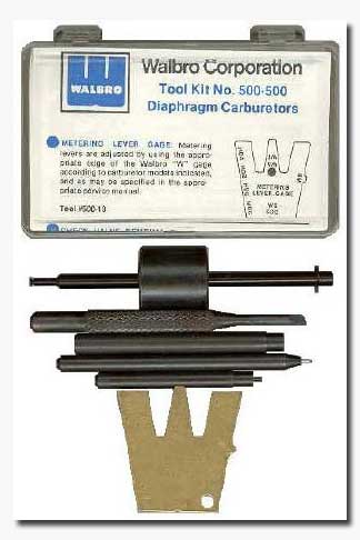
 When
you reinstall the needle valve assembly, you might want to check the metering
lever adjustment. There is a gage available from Walbro for this. (P/N: 500-13) I have also found that you can usually get a
really good setting by simply laying a flat screwdriver or a ruler over the
small ridges on either side of the arm tip and adjust so that the tip just
touches the screwdriver.
*** Remember on the metering side, the gasket goes on first followed by the diaphragm (metal backing plate facing towards carb body) and finally the four screw cover. On the pump side, it is pump first, followed by gasket then the single screw cover. This is important and if you get them reversed the carburetor will not operate correctly. ***
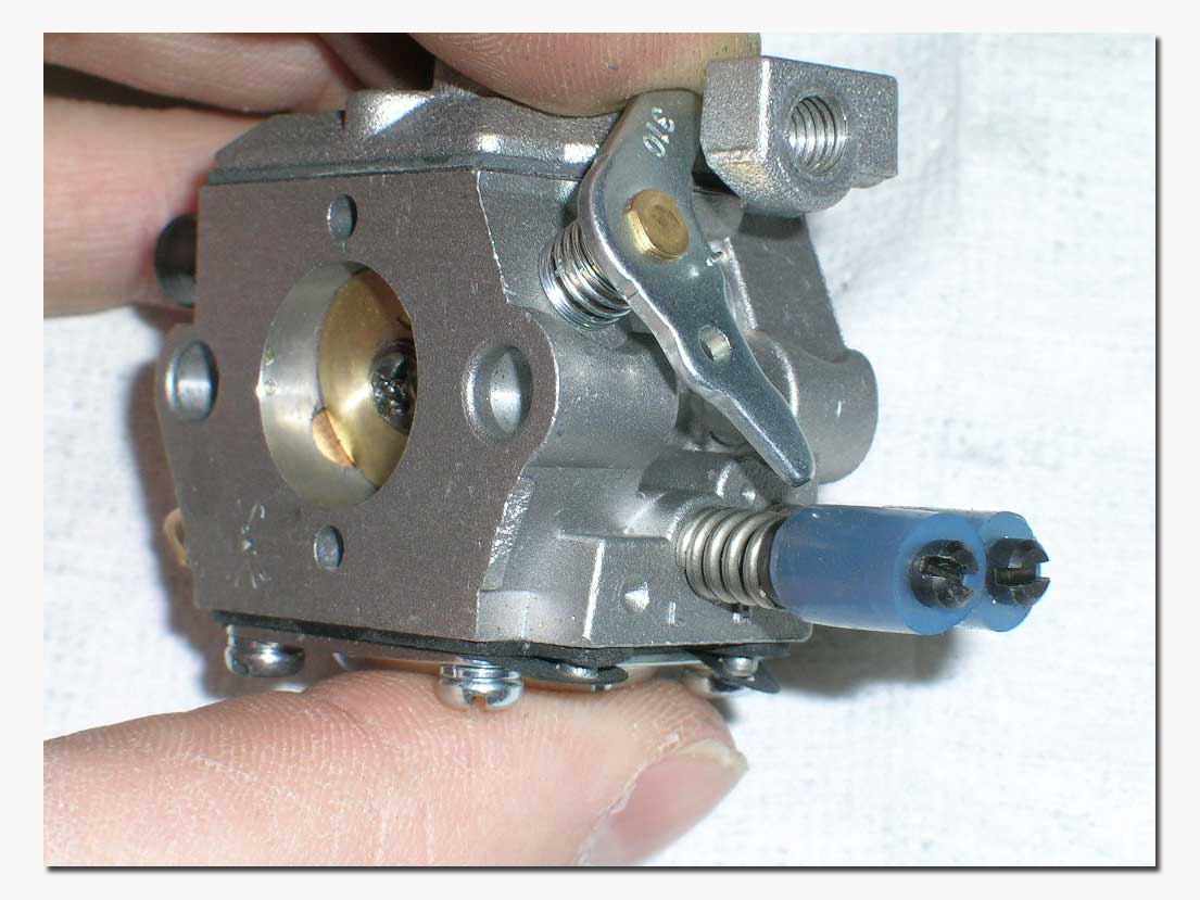
When you install the needles, do not over tighten them. It is also a good idea to slip a short piece of silicone tubing over the needles to prevent them from loosing their settings when the engine is operating. The two needles can then be zip-tied together for added insurance.

This completes our overhaul of the Walbro diaphragm carburetor! Hopefully this information will come in handy for a lot of Gas boaters out there, and allow you to do something you might have been reluctant to do yourself.
Happy Boating!

