Tech Article... by Curt Conrad
Translation by Andre Abtmeyer
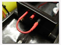
Learn how to make a foolproof switch that doubles as charging terminals for your radio box!
Switching on your receiver is easy today with all the available waterproof switches. But how do you charge your batteries without openning your taped and sealed radio box?
I will present my solution for this…an integrated power supply that is easy to make.
I start with a piece of electronic circuit board. The blank boards (epoxy cards with a thin copper layer on one side) are available at most electronic hobby shops. I cut a strip 2’’ long by ½’’ wide and drill 3 holes in it. Two of the holes have the same diameter as the gold contact connectors I want to use and one is for a wire.
After drilling the holes I break the continuity in the thin copper layer between the three holes by using a small file. Now there is no electric connection between the three blocks.
After that I solder 2 female gold connectors inside the 2 appropriate holes. Make it so that the open side of the connectors is showing on the uncovered side of the board. But attention! Some of the female gold connectors have a really small hole to the side for ventilation. Make sure that you close it during soldering.
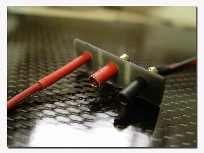
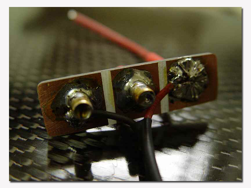
Through the third hole I run a piece of wire (1/8’’ diameter is more than enough) and solder it to the board. Now your board should look like this one:
Front side:
Backside:
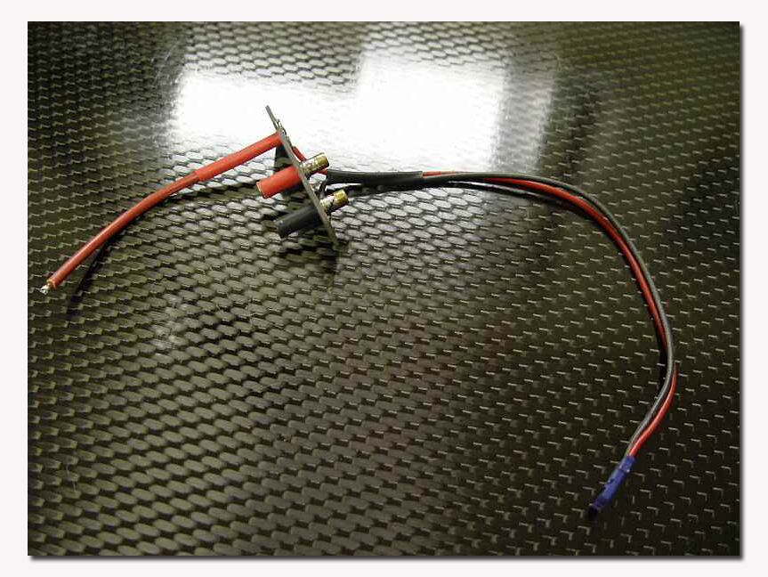
The next step is to add the wire for the receiver. I solder the positive lead (red) to the same terminal where the piece of wire is fixed (right side in the pic). The negative lead is soldered to the negative terminal of the board (left side in the pic).
Don’t forget to add some coloured heat shrink tube to the female connectors (red for the positive terminal and black for the negative terminal).
Your supply should looks like this now:
Now I drill three holes in the radio box where I want to add the supply. After that I glue the supply from the inside of the radio box. I use epoxy glue to do that. Don’t forget to clean and sand all surfaces before gluing together.
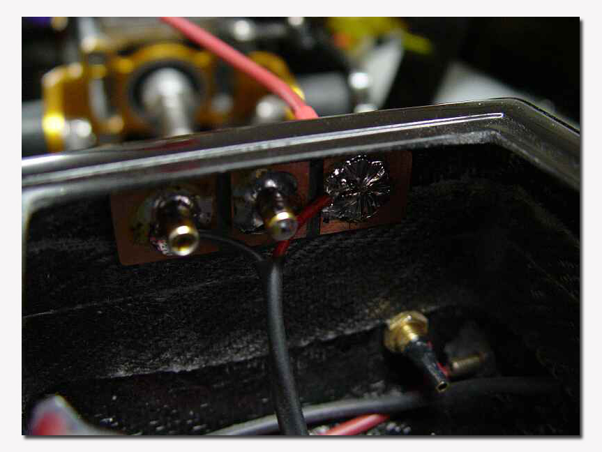
The next step is to add the battery to the supply. I solder the black wire to the negative terminal and the red wire to the free terminal (that’s the one in the middle with one of the female connectors). Don’t forget some pieces of heat shrink tube before soldering the cables to the terminals. After fixing the cables place the heat shrink tubes and shrink them over the soldered connections.
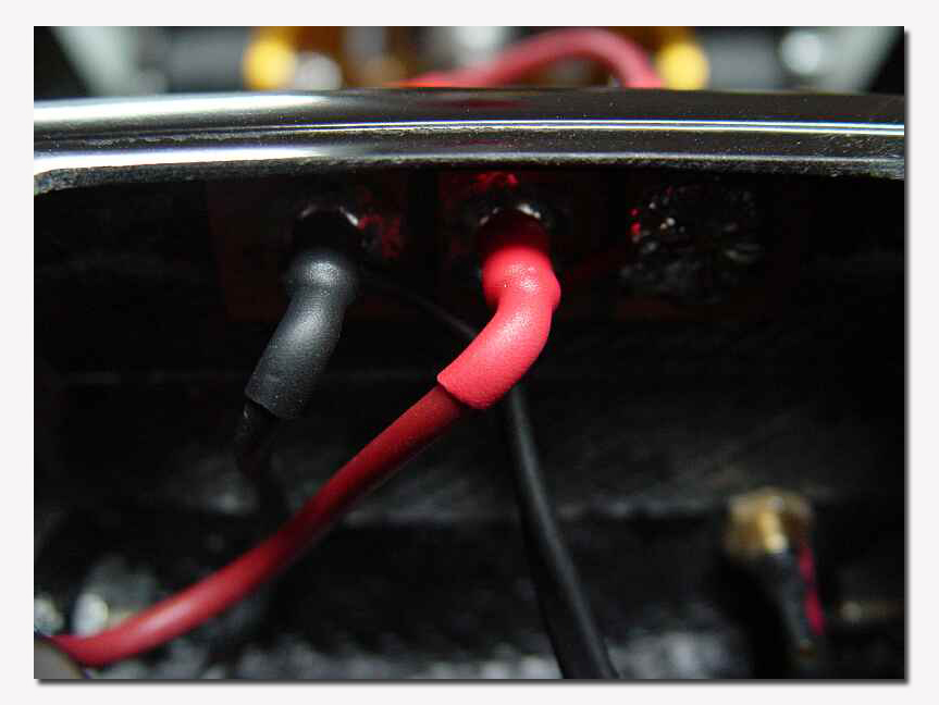
The last step is to solder a male gold connector to the end of the wire outside the radio box and that’s it!
To switch on the receiver you simply have to put the male connector the red female connector:
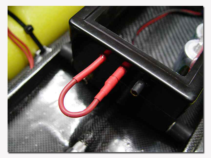
And remove it to switch off the radio:
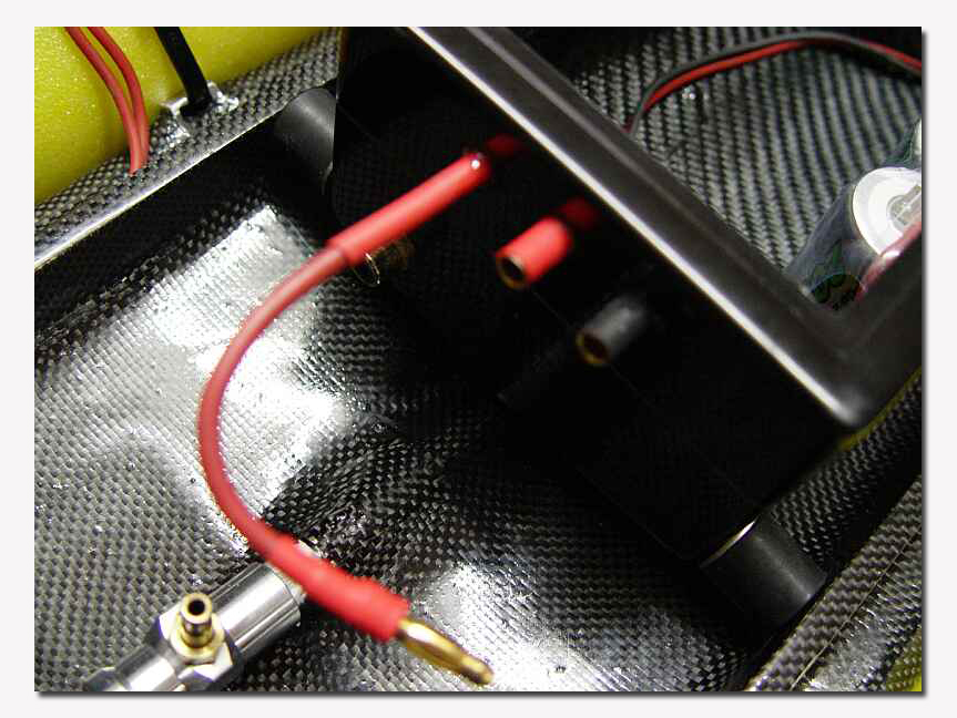
If you are confused and put the male connector in the black female connector nothing can happen. No short-circuit, no wrong connection. Why? Very easy: the receiver is now just connecting to the negative pole of your battery.
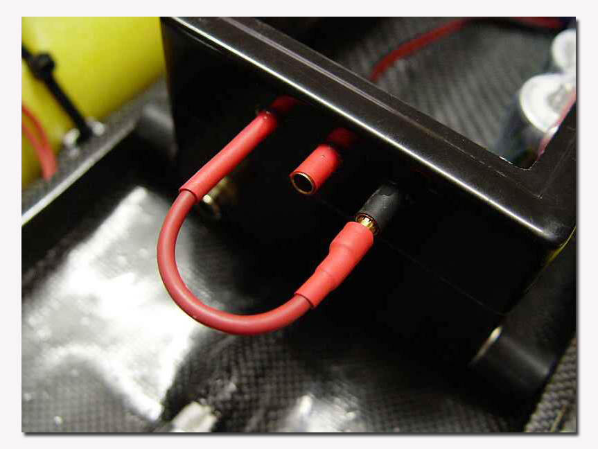
To charge your battery you simply have to connect the charger to the female connectors of the power supply. It is not necessary to open the radio box for charging when using a low current. If you want to charge the battery fast (by using a higher current) you should add a 3/16’’ hole in the lid of the radio box for ventilation. After charging you can just put a small piece of tape to seal the vent hole.
What are the advantages?
– Absolutely waterproof, no moving parts through the radio box to switch on the receiver
– 100 percent safe against short-circuits
– Reliable and safe
– Not necessary to open the radio box after a day of running (except if it is wet inside of course…)
– Easy to make yourself
Hope you like it.
This email address is being protected from spambots. You need JavaScript enabled to view it.

