Scratch/Custom Builds ...

Building process of a Custom Insane Mono...
See PART 2 of this build here...
I have been involved in model boating since the age of fifteen. My brother has watched me “play” wit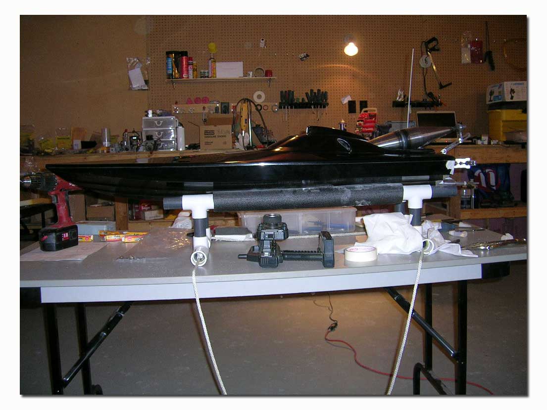 h these “little boats” from the start, but he never actually showed any real interest in them…until recently! Last summer I did some testing of a few boats at his cottage, and not long after he told me he was interested in acquiring a gas boat. He said he wanted to build something nice, a show boat that could also perform. He said it had to be fast! We agreed that a mono would be a good choice for a first boat and also best suited to the area where he would most often run the boat.
 With this information, I put together a short list of trusted manufacturers’ websites for him to visit, browse through the available hulls and get an idea of what he wanted to build. After a day or two he contacted me with his decision...he wanted the new style Insane Mono with cowl. We went ahead and placed an order with Jeff Michaud at Insane Boats for a custom all black mono with cowl. We also ordered all transom hardware from Jeff. As usual the ordering was fast and easy. I ordered just prior to the Orlando Winter Nats, so Jeff said he would get the order started and ship it out when he returned from the races…he did. A couple weeks later the Fedex man walked to my door with a big brown box containing the hull and hardware, all in top shape.
In this article I will simply highlight some of the building steps. If you would like to read our full review of the Insane Mono, you can see it in Issue 9. This article is being written simply to follow the progress of this custom build and to give readers some ideas. There are however some things that were done differently in the setup of this hull as opposed to the original we reviewed, and they will be noted.
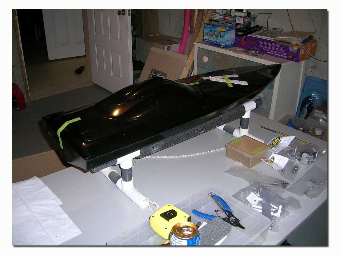
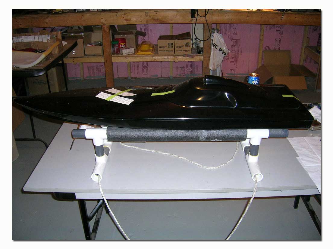
Here are a few pictures of the hull. I really like the fiberglass work on the Insane hulls. The inside is nice and smooth making for easy clean up after a day at the lake. These hulls are laid-up strong, with a great quality gelcoat. They are of the shoebox type.
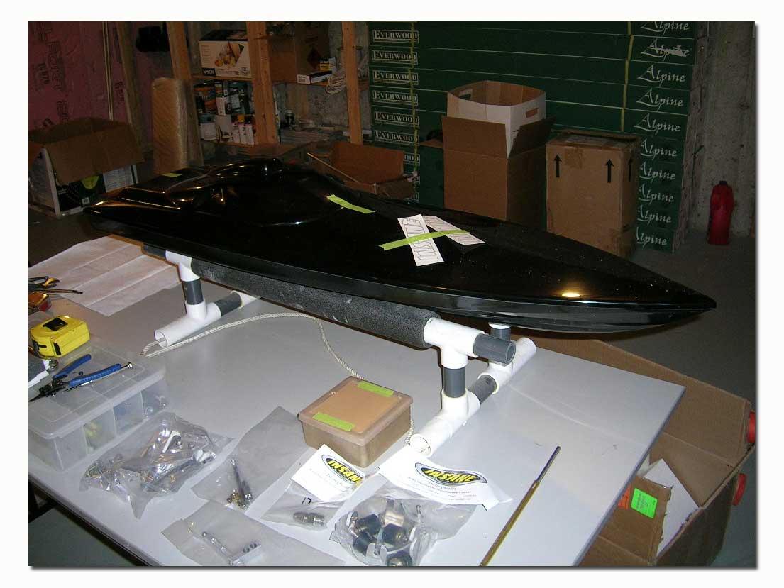
The hardware package included all the transom hardware except for the tuned pipe mount. The drive has changed from the original design. This one no longer utilizes the turnbuckle adjustment. To adjust the angle of the drive you simply have to loosen the screws securing it to the mounting brackets. The mounting bracket holes are slotted for up and down adjustment of the drive on the transom. This is a high quality drive that is simple in design yet looks good and will be virtually bullet proof. It can accommodate both square and collet drive setups.
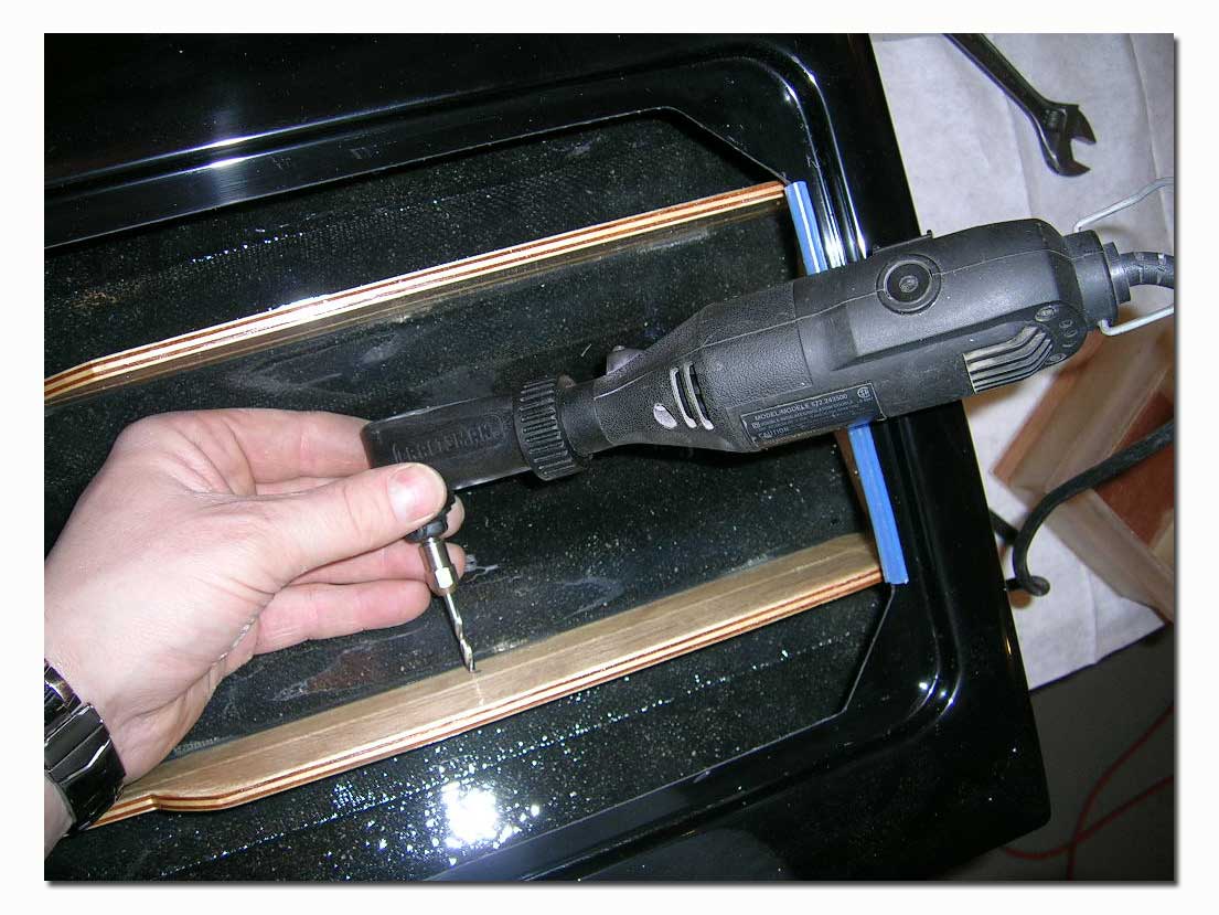
Also included is a rudder and extended bracket to position the rudder at the proper distance from the transom. A nice change to the rudder blade is that it now has a water pickup on both sides of the blade for positive water flow no matter if turning left or right. Both pickups are common to the same water outlet at the top of the blade. ***The water passage is pre-drilled 1/8" *** The rudder bracket is machined of a single piece of angle aluminum.
You will also notice that there are no trim tabs included in the kit. This is because the Insane mono requires no such tabs for proper handling. The supplied turn fin is pre-sharpened and ready to use. Be careful when handling the turn fin, I learned the painful way!
We also ordered a set of motor mounts, a T-bar, a square drive, a flex cable a stuffing tube and a prop shaft assembly from Insane. Make sure to specify what type of drive you plan on using (square or collet) when ordering and check with Jeff for any items that may be required to finish the setup. Insane can set you up with all the required parts.
The build…
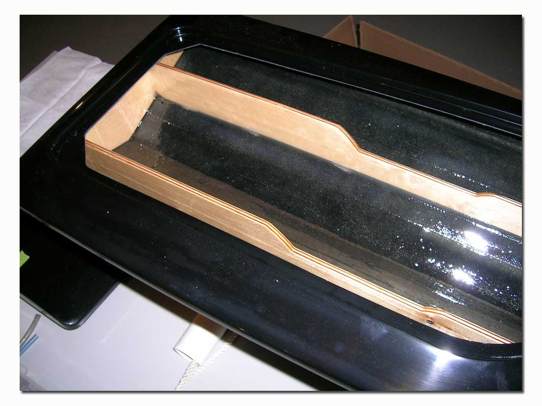
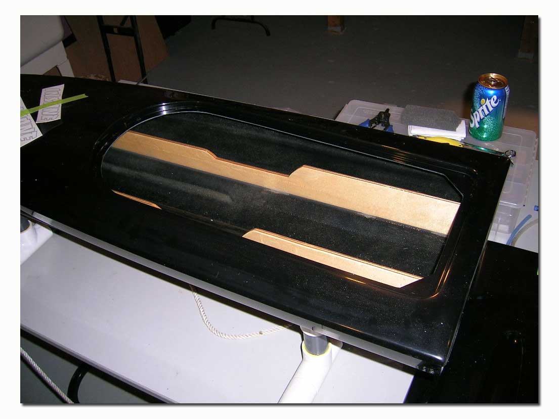
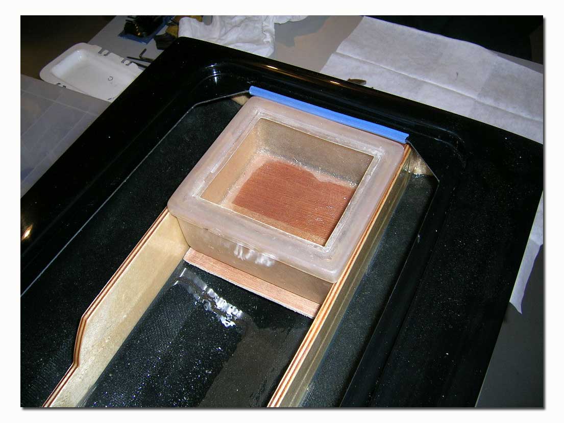
The first thing I did was to prepare the radio box. I did this first to give it time to set properly before I started the actual rigging of the box. I use a piece of ¼” plywood cut to size and epoxy it to the underside of the radio box. I sanded the box and cleaned with acetone prior to gluing the plywood to it. The piece of plywood is cut to the same width as the box, and slightly longer lenthwise. I let about ½” stick out the front (bow side) of the box. This will help with securing the box in the hull later. The wood backing plate will be sealed during the painting process of the hull.
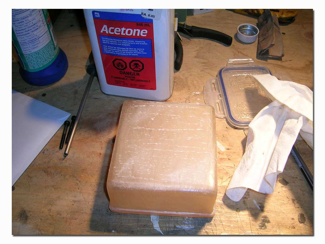
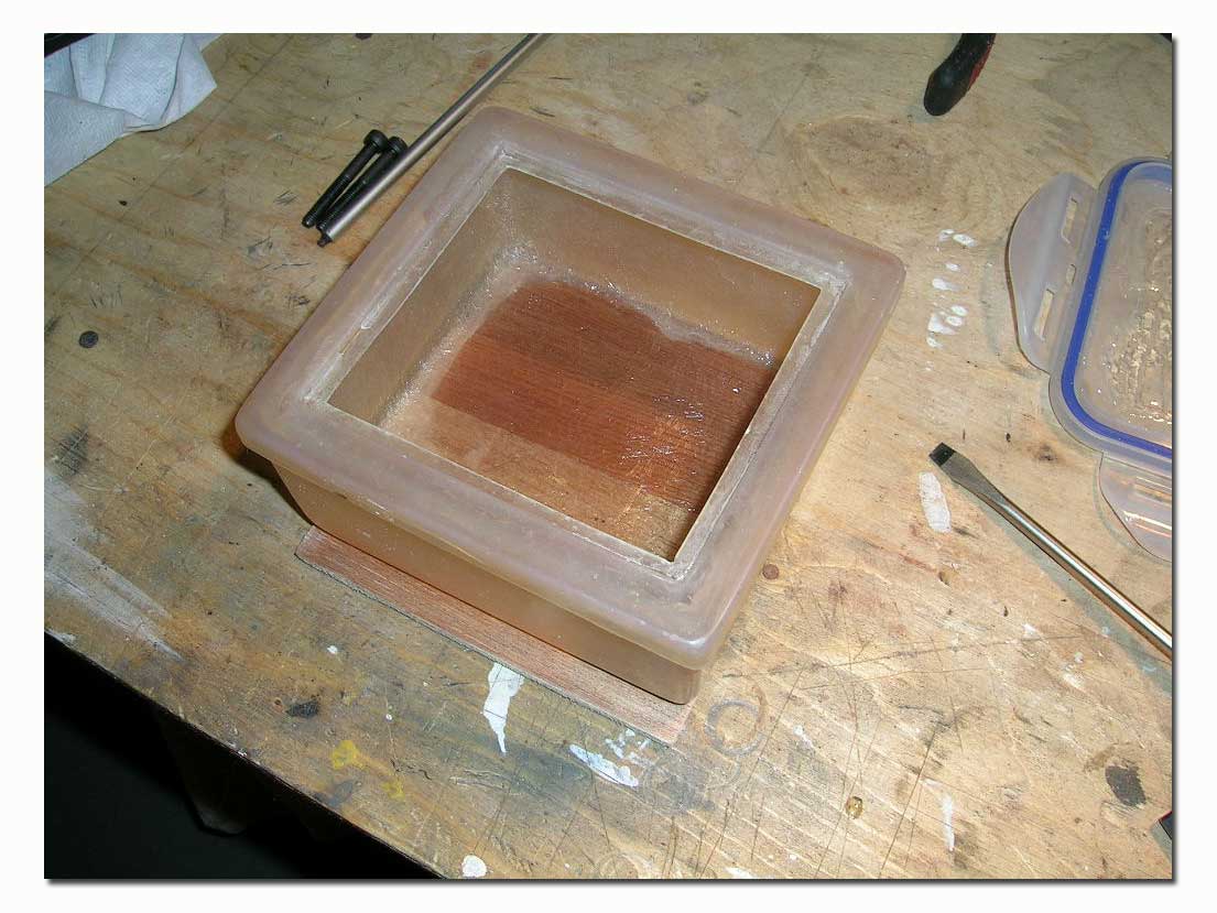
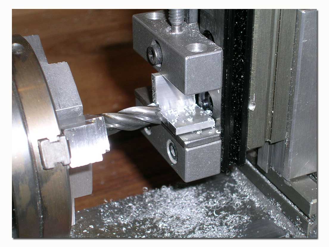
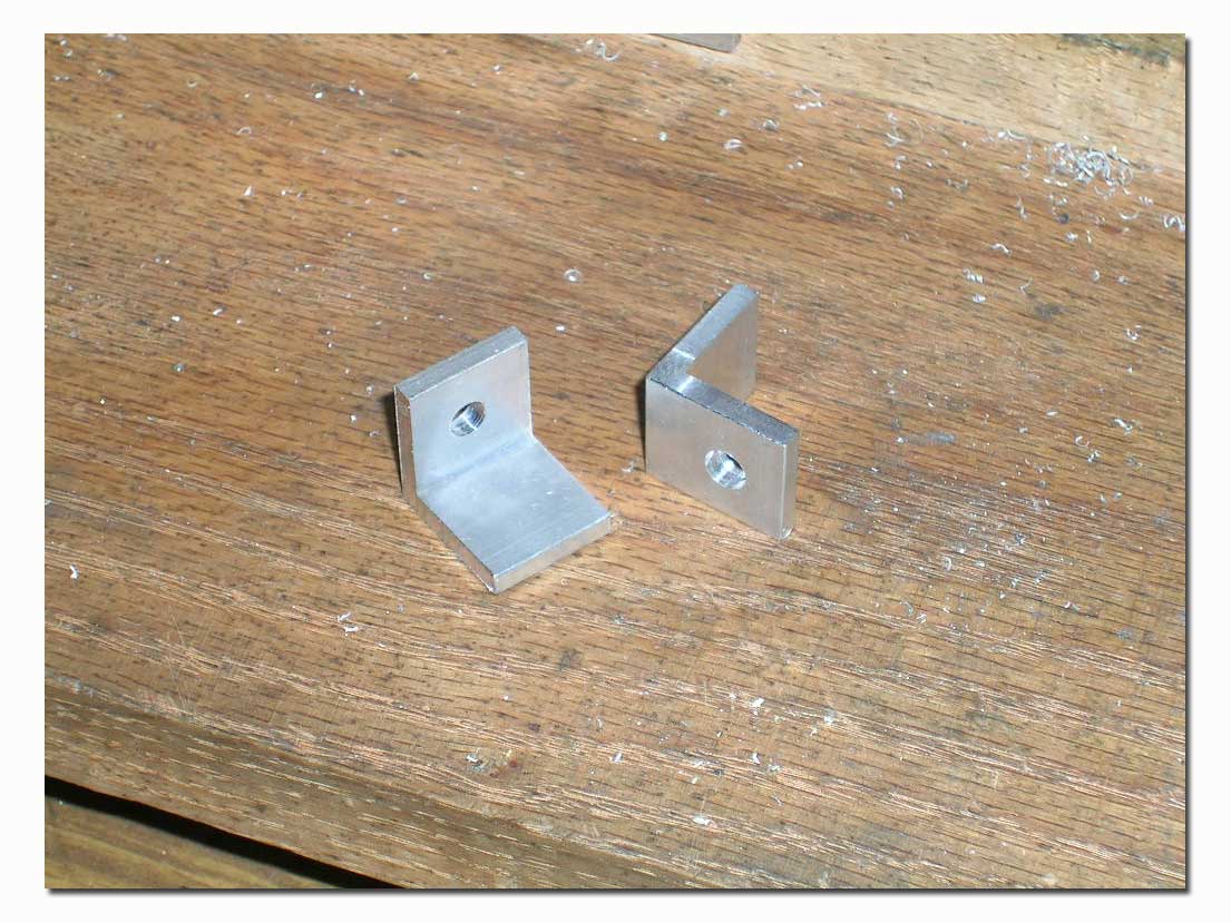
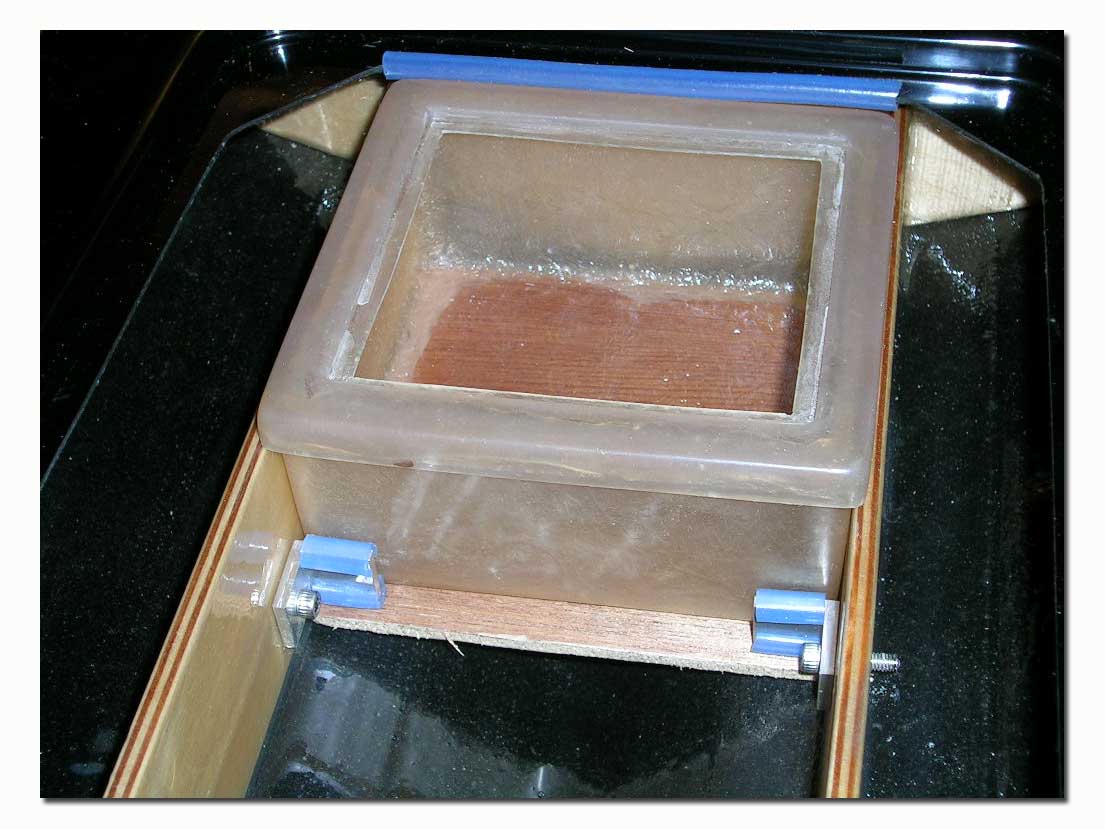
I made a pair of box supports using some short pieces of aluminum angle. These will be mounted to the stringers and hold the radio box in position in the hull.
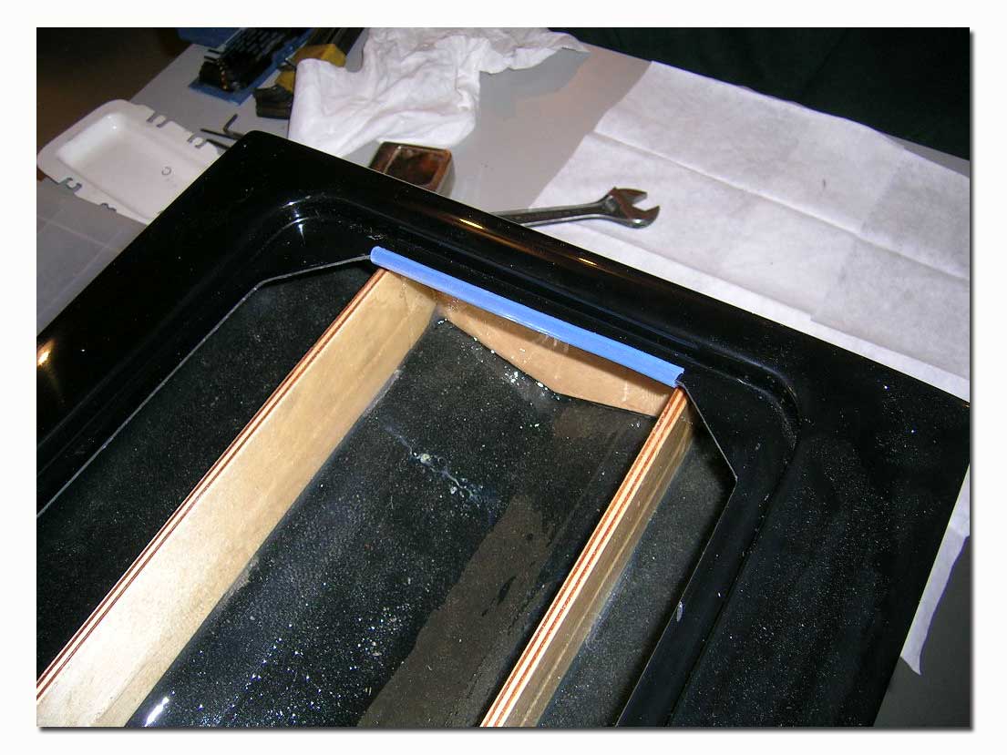
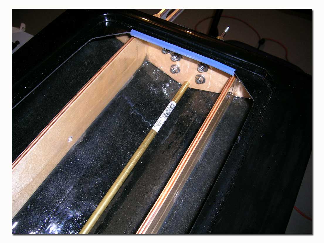
This is the way I mount the radio box in the Insane monos. To date this system has worked very well for me. After laminating the ¼” plywood under the box, if you lay it in the hull and push it up against the back deck you will notice that it won’t slide under the deck. So for the back support I simply slit a piece of silicone tubing lengthwise and slip it over the lip of the deck. The radio box then butts up against the deck.
I then install the two front brackets I just made. Position the box tightly in place and test fit the brackets and mark the stringer where you need to drill for the bracket bolts. I also use pieces of silicone tubing on the brackets to cushion for vibrations and keep the brackets from wearing grooves into the radio box. If you do it so the brackets are tight against the box, you will find that the box is held very firmly in the hull. I did a similar setup on my original Insane mono, using an aluminum back plate.
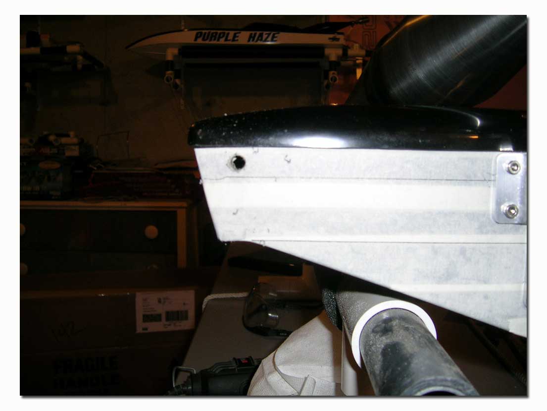
With the radio box mounting taken care of, I moved to the transom of the hull. As always, I covered the transom with some masking tape. This helps prevent gel coat chipping when drilling the holes, and also makes it easy to temporarily write on the transom. The first line I draw is the horizontal plane, taken by drawing from chine to chine. I then make a parallel line above it for reference purposes when installing th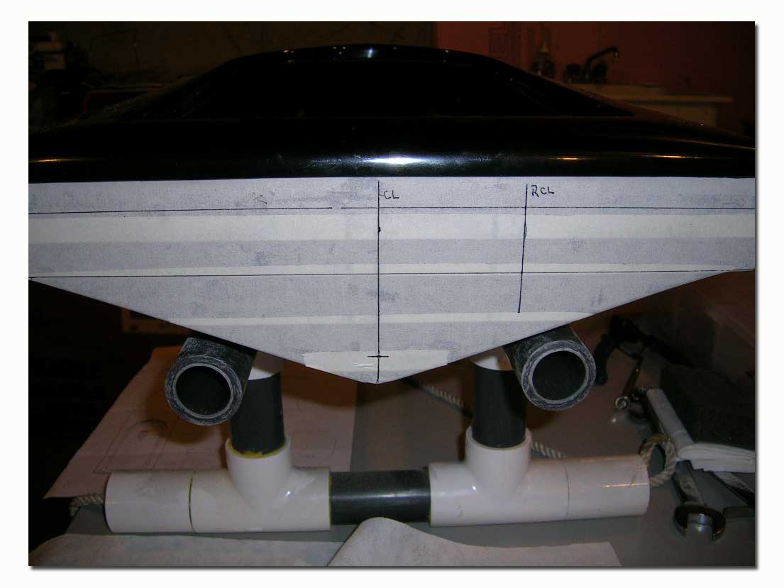 e hardware. I then find the hull’s centerline and mark it using a square and the horizontal plane line as reference. I then find the location for the rudder’s centerline and mark it using the same method. When I first marked the transom I set the rudder’s centerline at 2- 3/16” from the hull centerline. This was the setting I used on my original Insane mono. I later noticed that the new hardware would not allow the rudder to be placed this close to the drive. After talking with Jeff about this, he suggested I mount it inline with the starboard stringer, so I later drew in the new rudder centerline at 2.5” from the hull centerline. This is where the rudder was ultimately mounted for this build. According to Jeff either position works well.
First Holes…
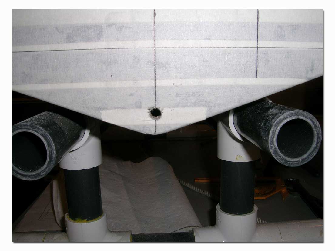
The first and probably the most important hole to drill in the transom is the hole for the prop shaft. This hole needs to be drilled on the hull center line at ½” from the keel. Measure this one accurately and mark the transom. I use a smaller 1/8” drill bit to make the pilot hole. I then drill it open with a ¼” drill bit. I then install the prop shaft or a ¼” rod or drill bit in the drive using the appropriate bushings (depending on the drive type). The prop shaft or rod is left to protrude from the front end of the drive. I then hold the drive against the transom with the prop shaft in the hole I just drilled in the transom. Then I mark the transom for the drive mounting holes. I use the horizontal lines I made on the transom for references in positioning the drive straight. With the prop shaft in the hole, you cannot get the drive position wrong, so you are certain the prop centerline will end up right where you want it to be. I then drill the holes and mount the drive. After the drive is mounted, I remove it from the brackets and open the transom hole large enough for the stuffing tube.
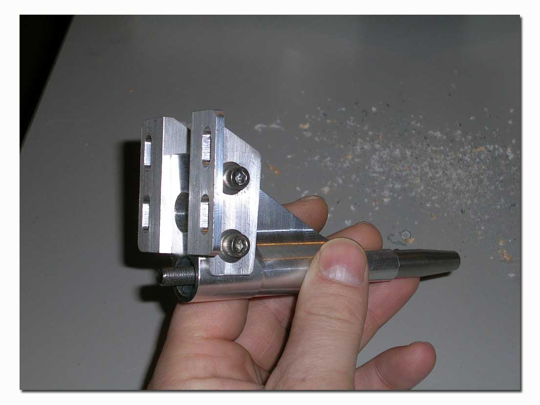
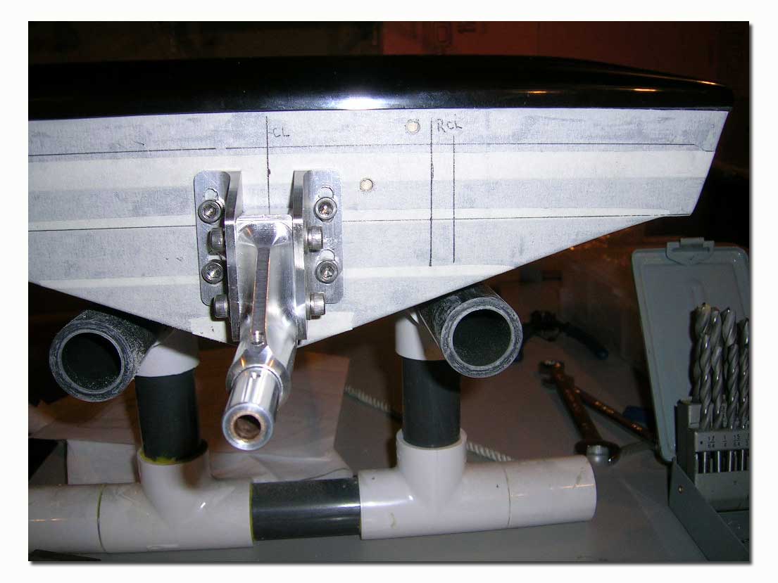
Next comes the rudder. I install the rudder bracket flush against the lip of the top deck. The rudder centerline should line up with the mark made on the transom for this purpose. I use the horizontal lines as reference for positioning the bracket correctly. This is important as you want the rudder to be perfectly vertical in the water. I hold it in place on the transom, mark one hole then install the mounting bolt. Prior to drilling the other three mounting holes, I double check the position and tighten the first bolt. Then I drill the other three and mount them.
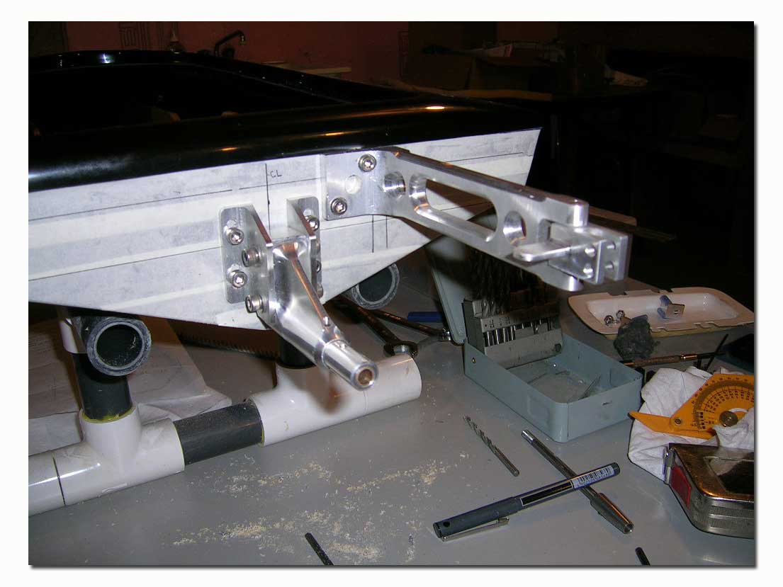
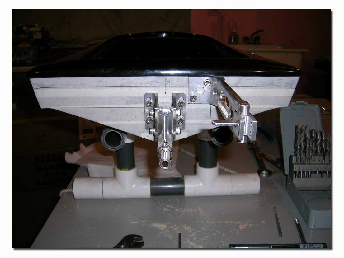
With the bracket in place I then drilled out the pushrod hole.
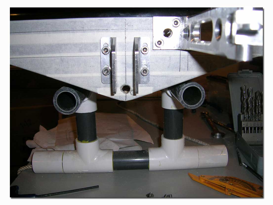
I then install the drive into place with the assembled prop shaft and fit the stuffing tube in the transom. This was actually my first time setting up a mono with a square drive setup. I liked the fact that even with square drive, this drive allowed for the stuffing tube to protrude a little bit inside the drive. This should eliminate the inherent “grease all over the transom” downside typical of many square drive setups.
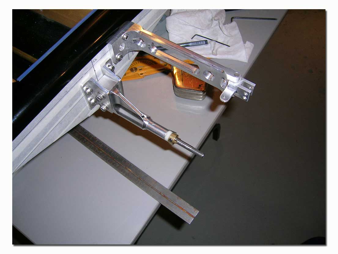
I drilled the transom for the engine mounts and temporarily installed the engine. I also installed the square drive on the engine. I then measured the flex cable and cut it to length. I dry fitted the cable to the prop shaft and into the square drive at the engine. With everything in place I positioned the T-bar and marked the stringer for drilling. After securing the T-bar, I checked everything for fit and clearance including the radio box.
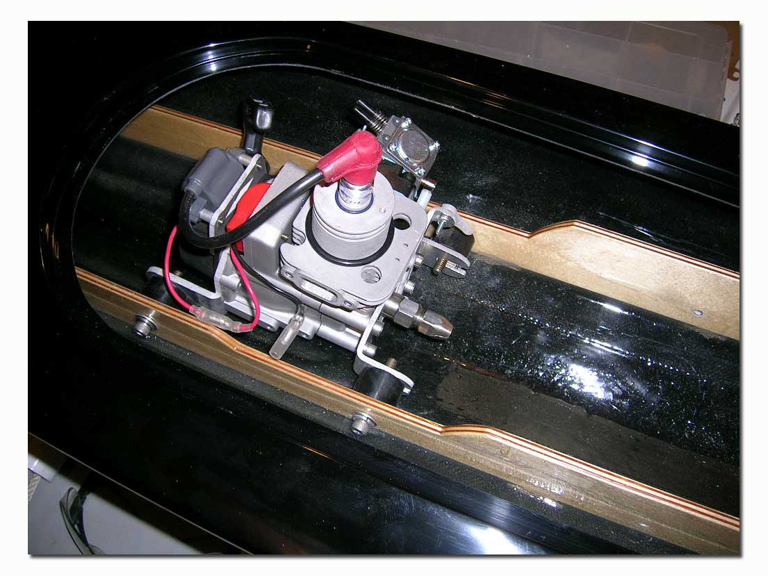
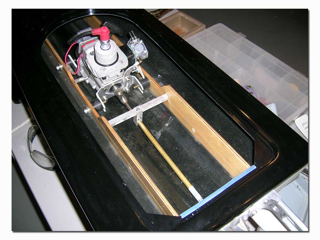
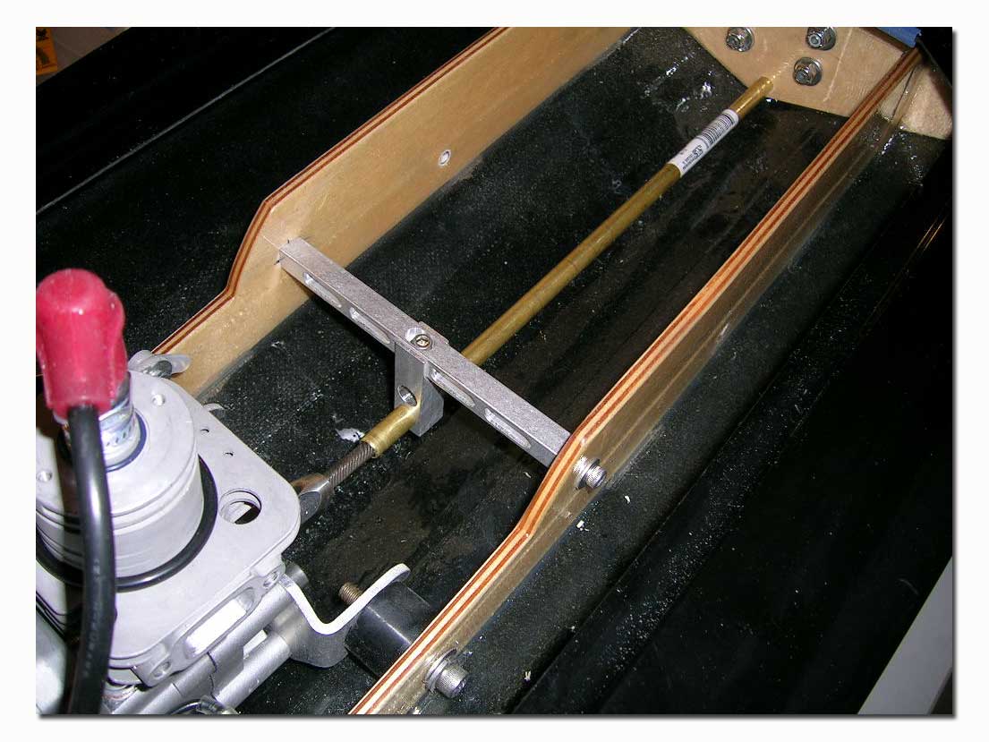
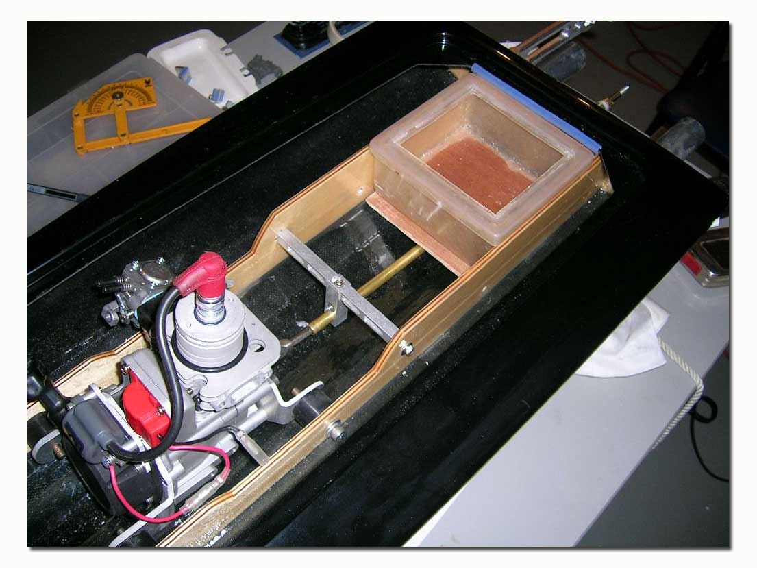
The next step was to install the header to the engine and put on the tuned pipe to find the location for the tuned pipe bracket. We used a Speedmaster tuned pipe mount. The pipe used is a Needforspeed Hobbies steel 2” band pipe on a 100 degree header. This is a great performing tuned pipe. I have found however that it does radiate much more heat than the typical aluminum pipes, so you must allow for proper ventilation and clearance in the hull. When using 100 degree headers the Speedmaster bracket must be bent a little bit to match the angle of the pipe.
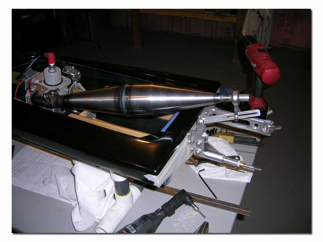
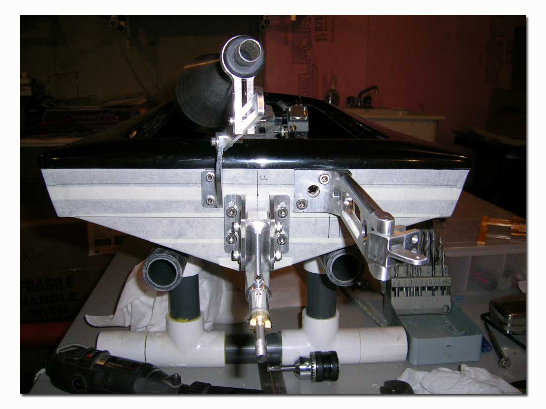
I then installed the turn fin to the transom and drilled a ¼” drain hole on the opposite side of the transom. The turn fin is mounted with the fin even with the outer edge of the spray rail, and at 90 degrees with the bottom of the hull. The fin should stick out 1.5 inches below the outer edge of the spray rail.
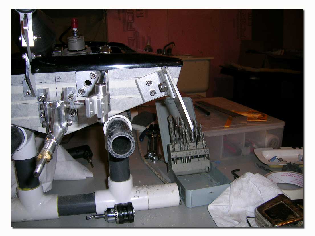
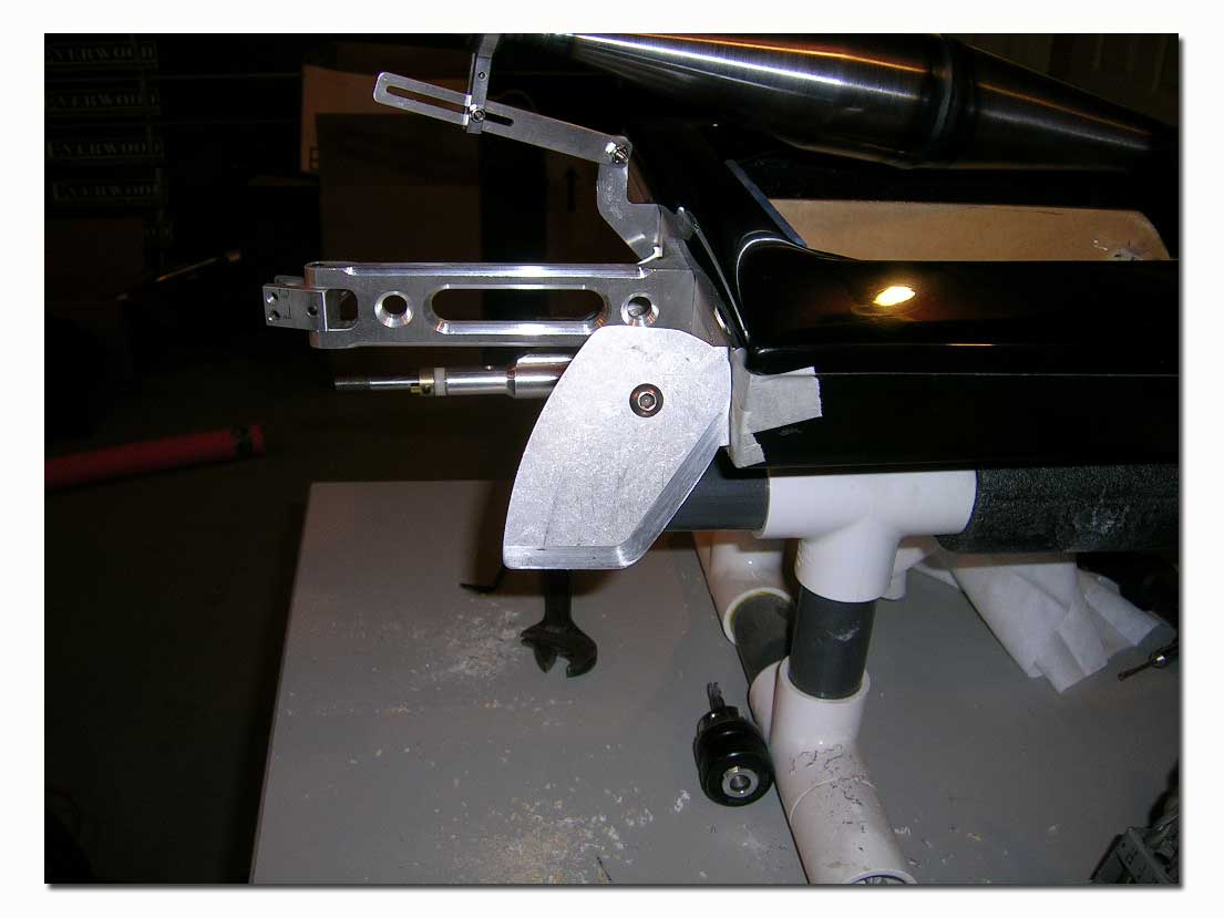
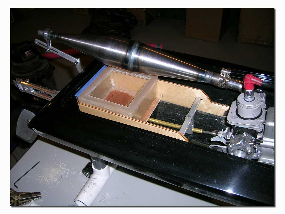
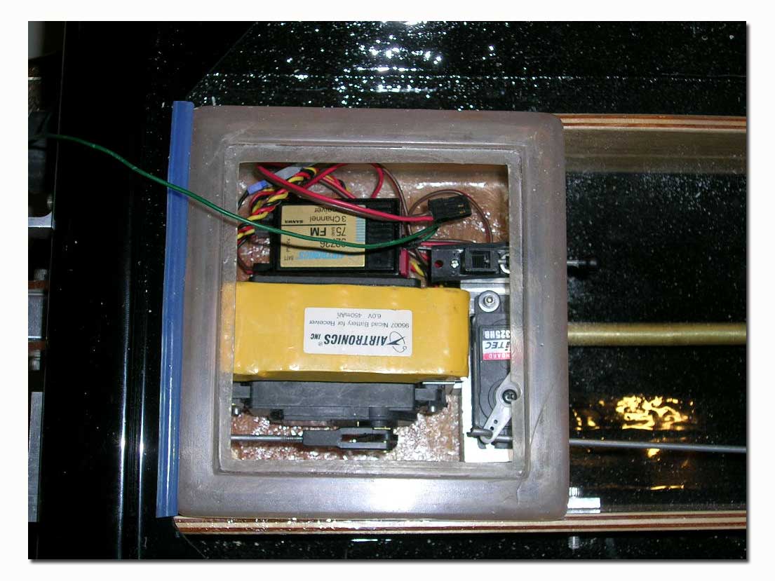
I then proceeded to the rigging of the radio box, servos and linkages. Notice the straight line linkages for both throttle and rudder.
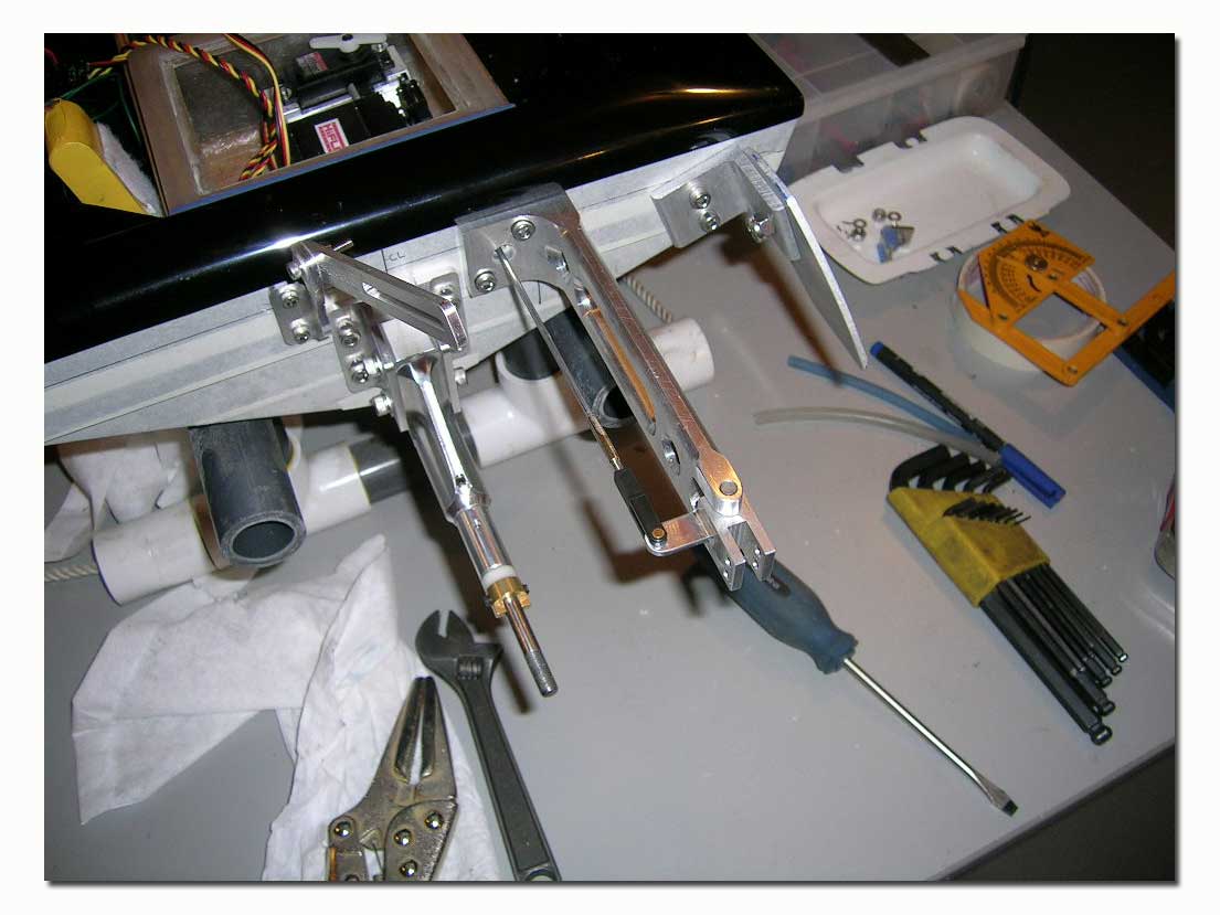
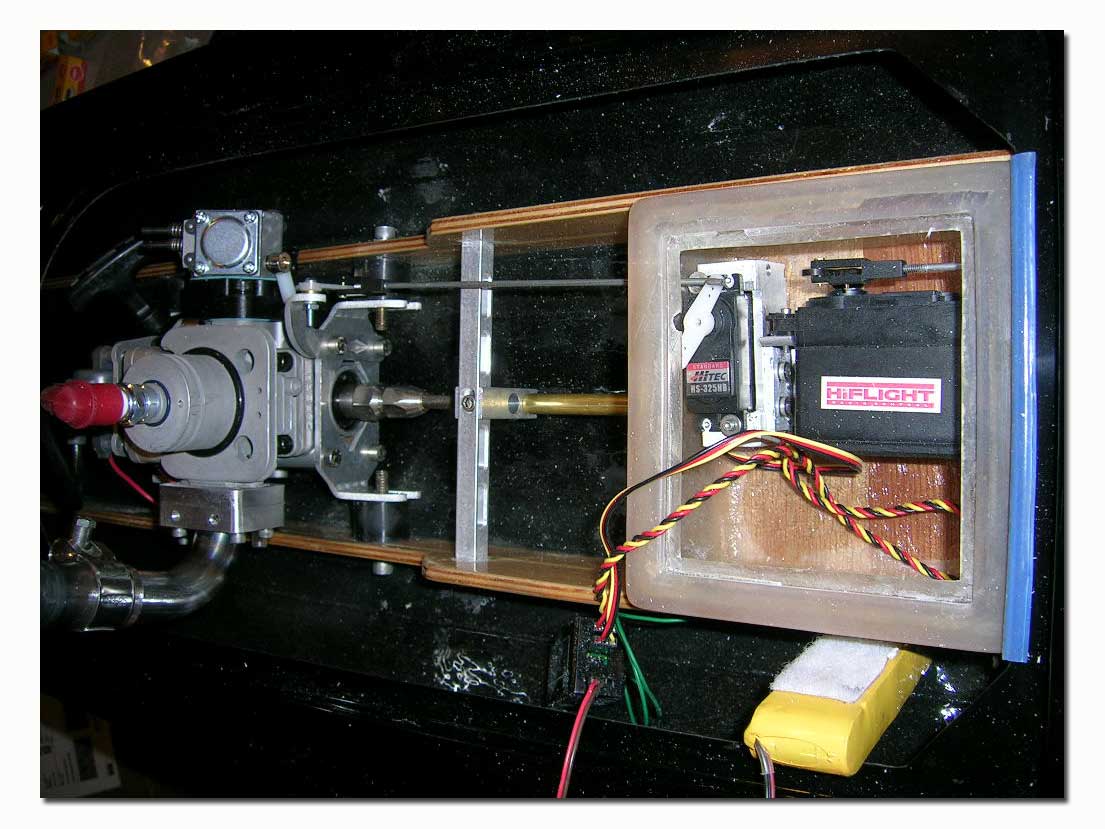
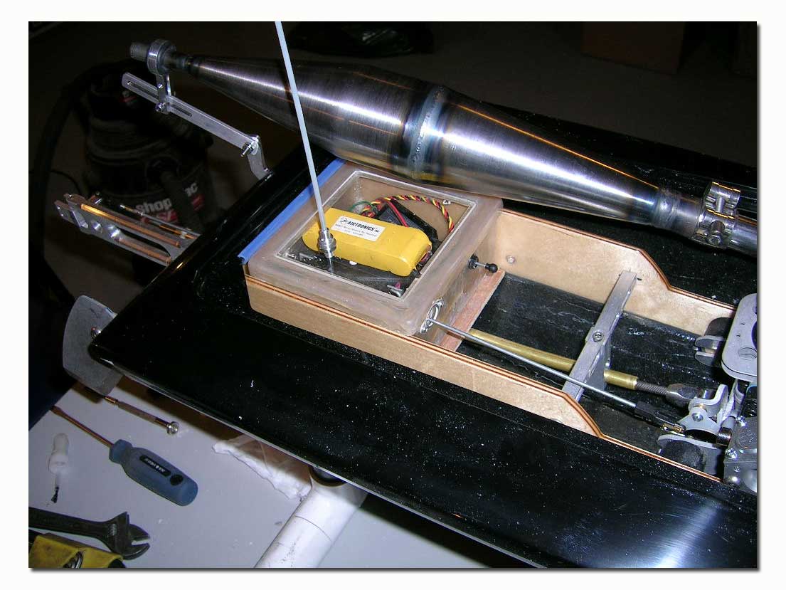
Next came the time for the scary part…fitting the cowl! I started by installing a “pin” to the cowl. For this I simply drilled a hole in the front lip of the cowl and used a large stainless steel screw in the hole, sticking out the front. I then “screwed” a piece of silicone tubing onto the treads of the screw. I also used some epoxy on the inside of the cowl lip to reinforce the area where the screw is and to prevent it from coming loose. I then test fitted the cowl on the hull and marked the area in the deck for the hole to accept the cowl pin. The rear of the cowl will be held in place with some rare earth magnets.
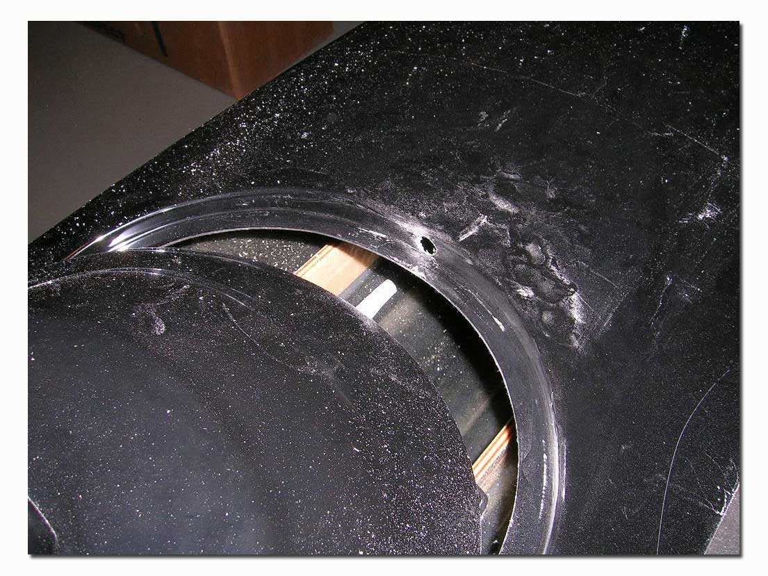
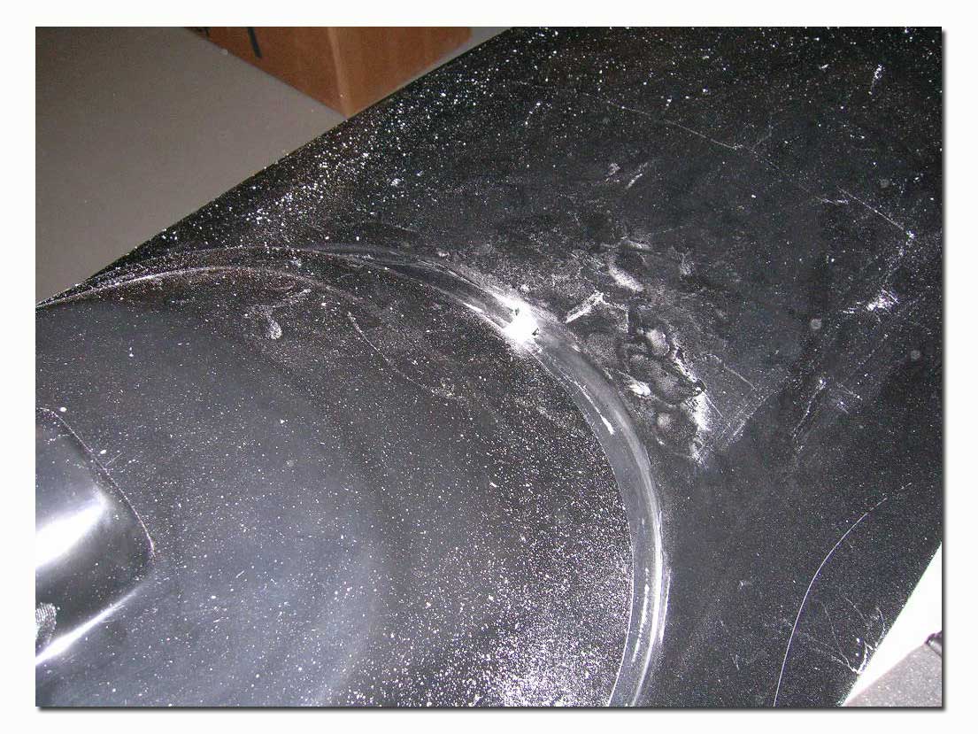
This done, I masked up the area where the tuned pipe cut-out needed to be and cut the cowl. Do this a little at a time, test fitting the cowl very often and making small cuts until the fit is as desired. I use a small milling bit in the Dremel tool for the rough cutting. To finish up I use a sanding drum and for smaller radius areas such as the air ducts, I finish up with a conical sanding stone, all with the Dremel. Be very careful when cutting the cowl…you can’t take it back if you cut off too much!
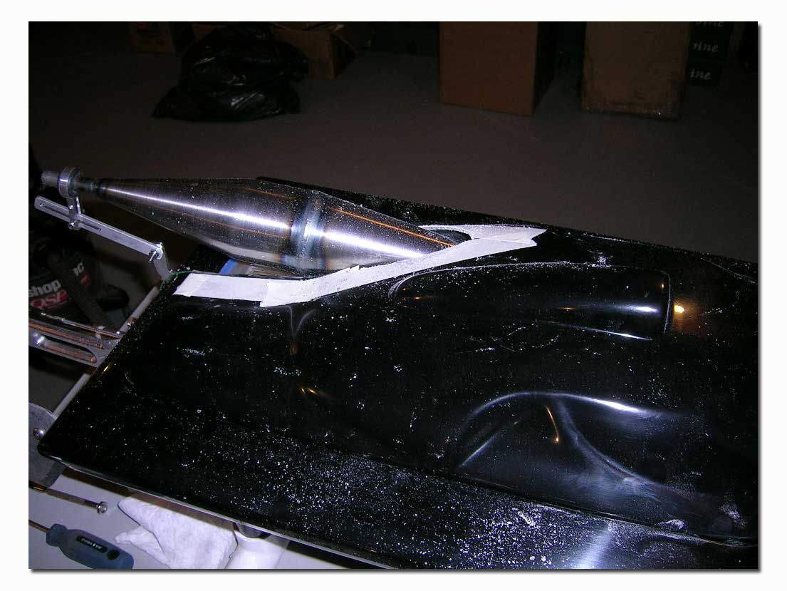
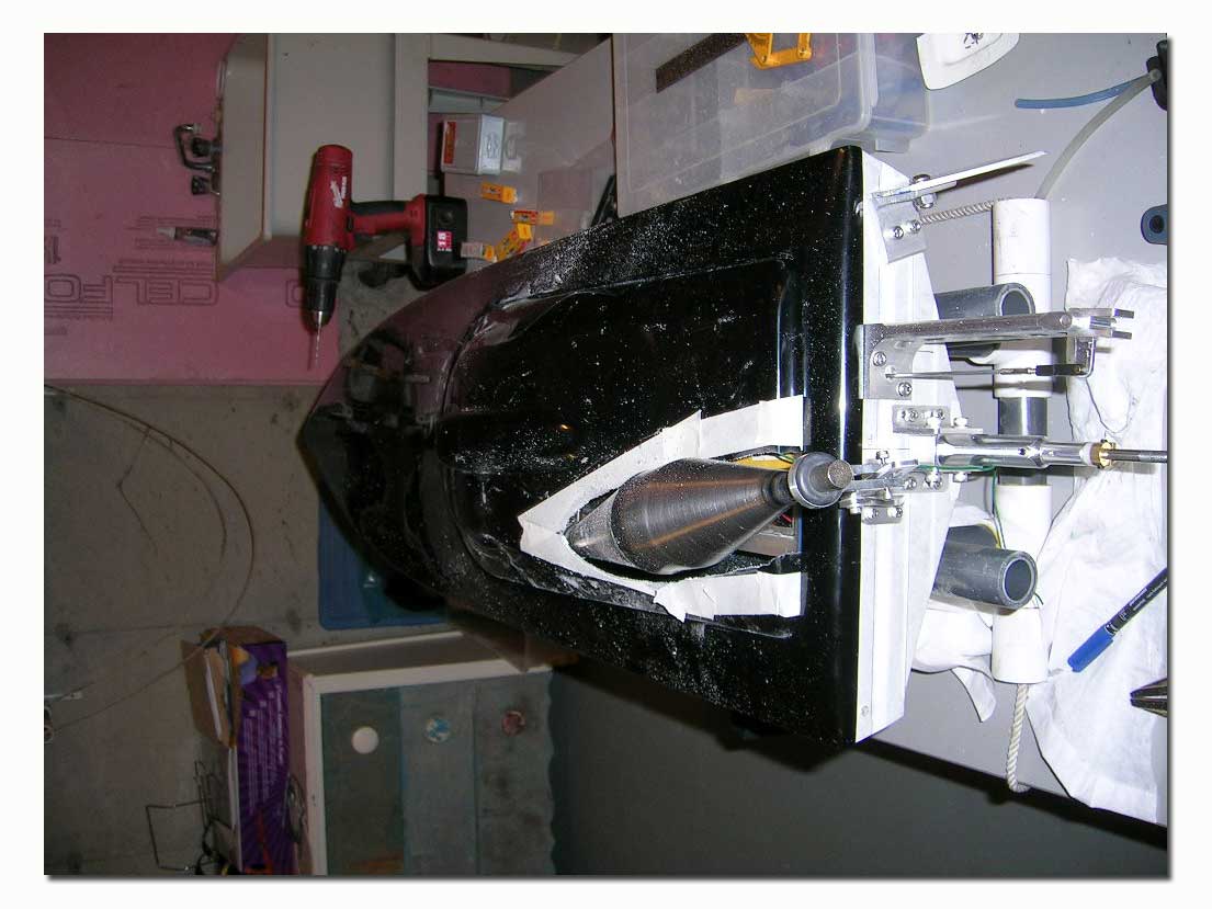
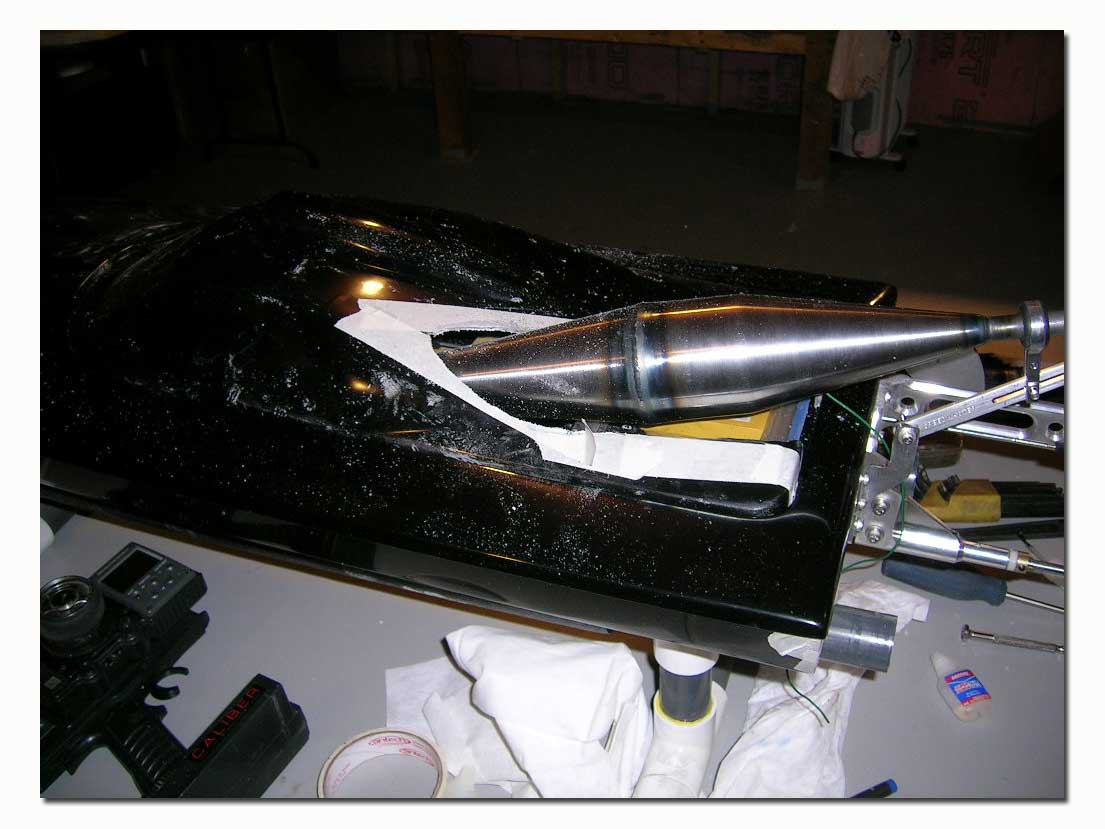
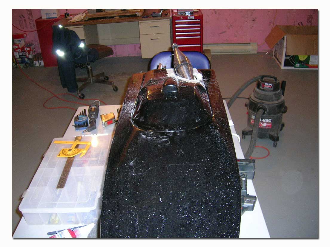
Below are a few pictures of the finished product.
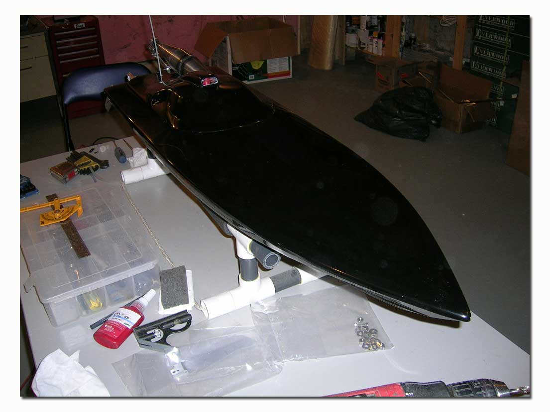
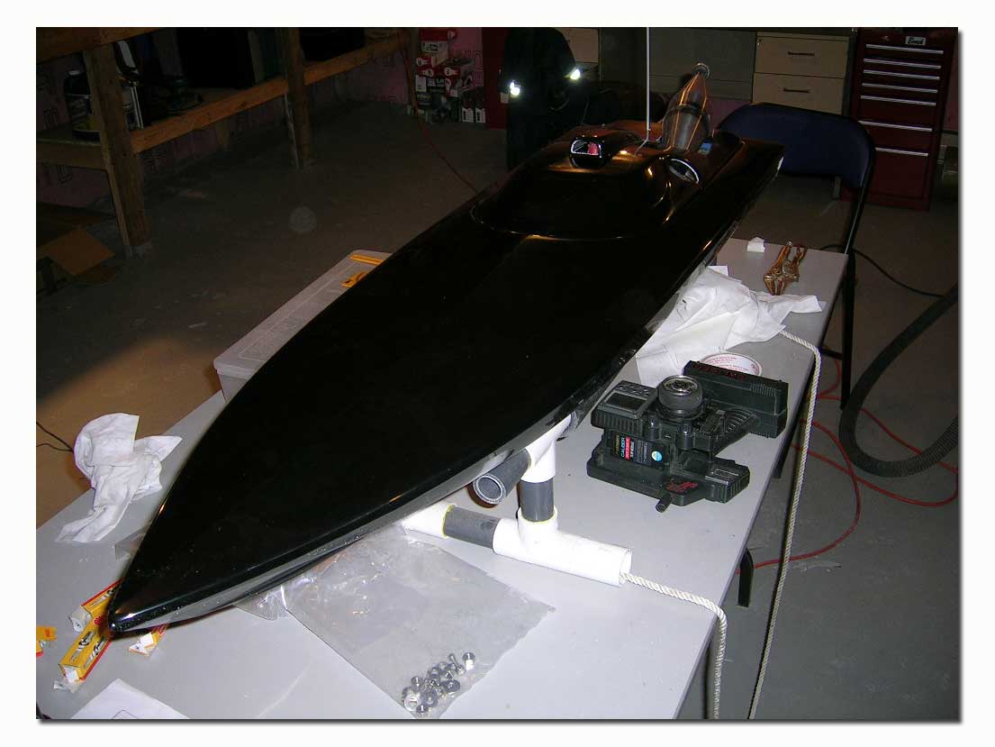
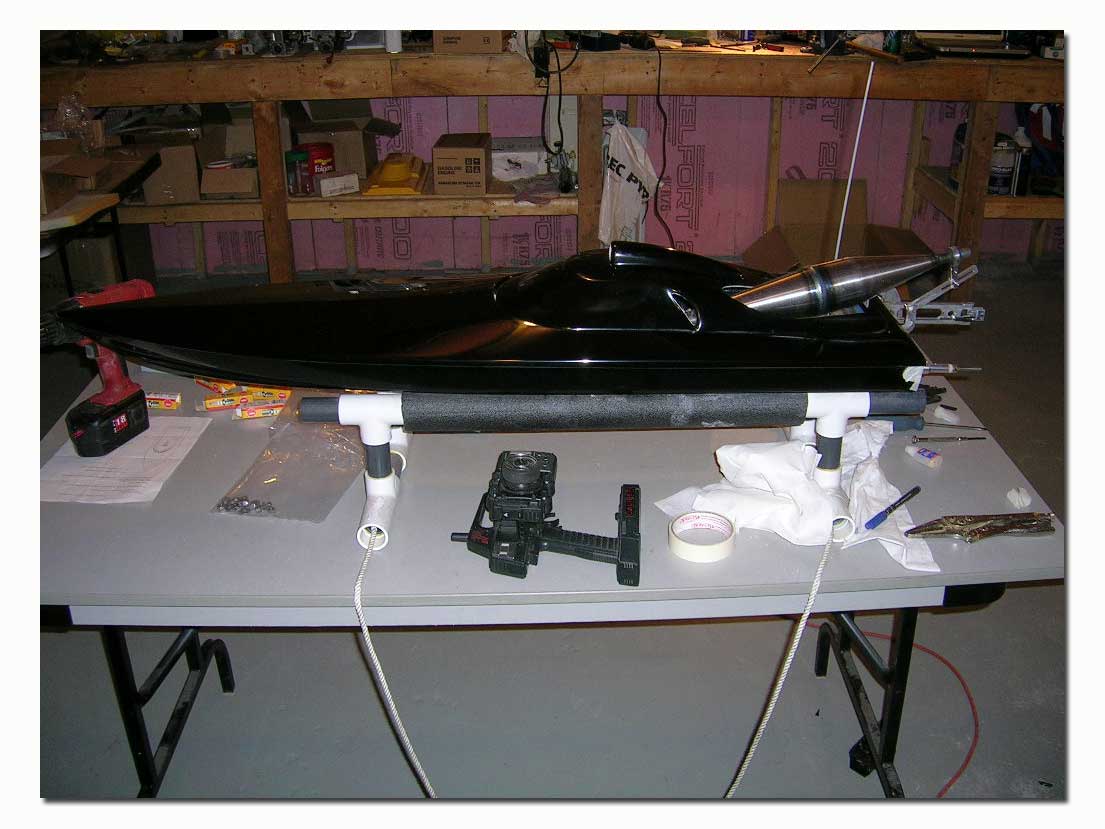
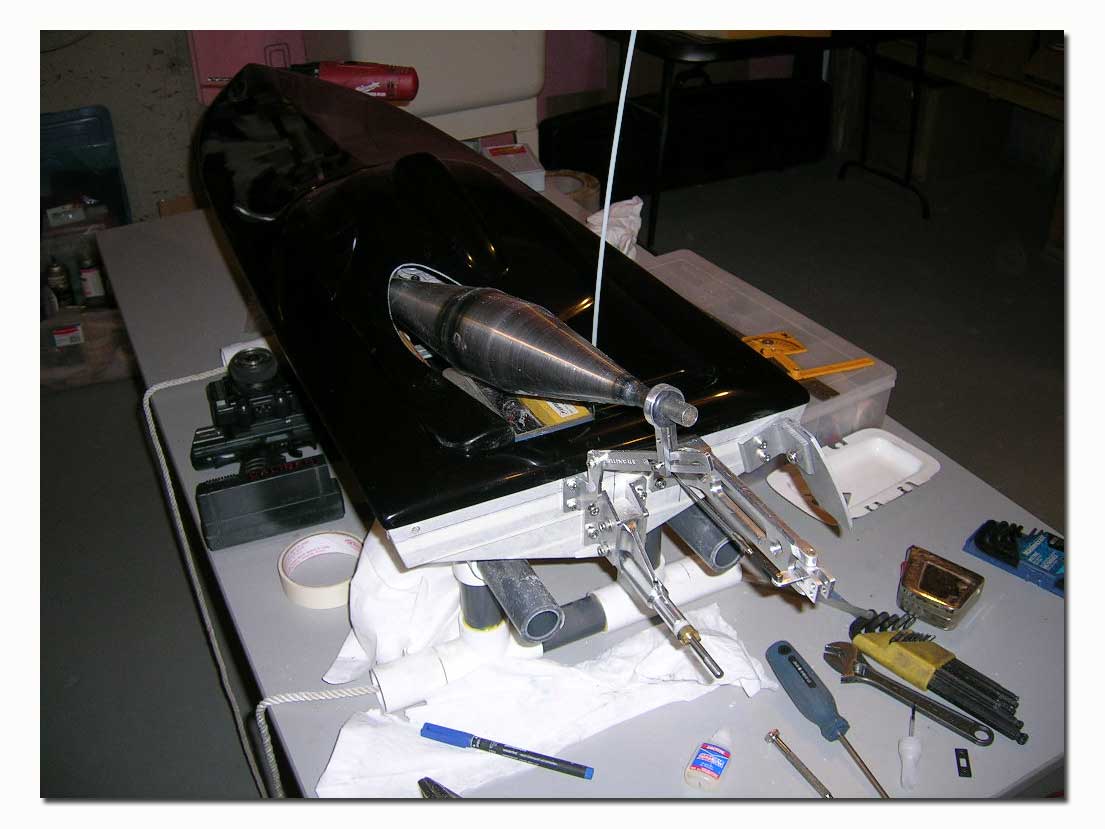
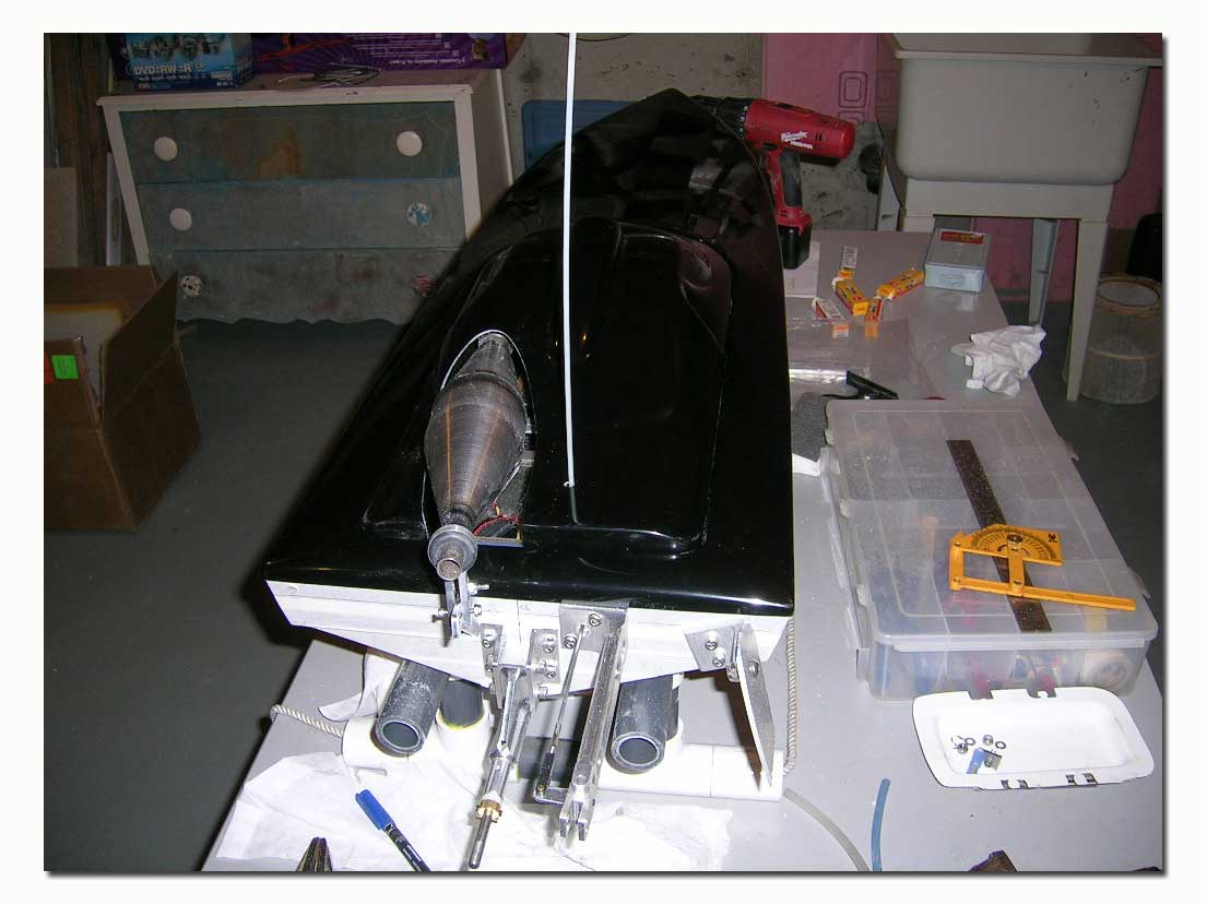
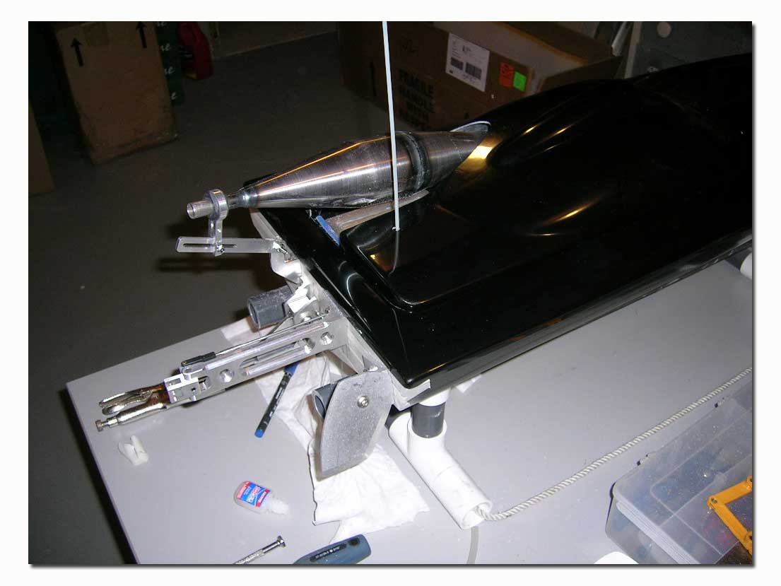
The hull will now be stripped bare and sent to the painter. All the aluminum hardware is going to the anodizing shop and the steel tuned pipe and header are going for chrome treatment! In an upcoming issue of MGB I will do an update on the progress of the build. The paint scheme has been chosen, and it should be awesome!
Happy Boating!
Suppliers for this build...
- Insane Boats - Hull and Hardware
- Needforspeed Hobbies - engine and tuned pipe
- This email address is being protected from spambots. You need JavaScript enabled to view it. - Muffler
- Rocket City Racing - Misc. Parts
- Great Hobbies - Misc. Parts

