Product Review Article ...

Read our review of the latest racing catamaran by Seaducer Boats!
(pictured here: Chris "JUICR" Rupley's Seaducer Cat catching air at full bore!)
Download the Seaducer Cat Manual here!
Seaducer Boats are based out of Ft. Lauderdale Florida. Owner Jerry Crowther is very well known in the racing community. Holder of several world records, he has built a reputation as one of the best racers out there. It is not surprising that his boats are design from scratch as pure racing machines, and this new catamaran we are reviewing is probably one of the finest examples.
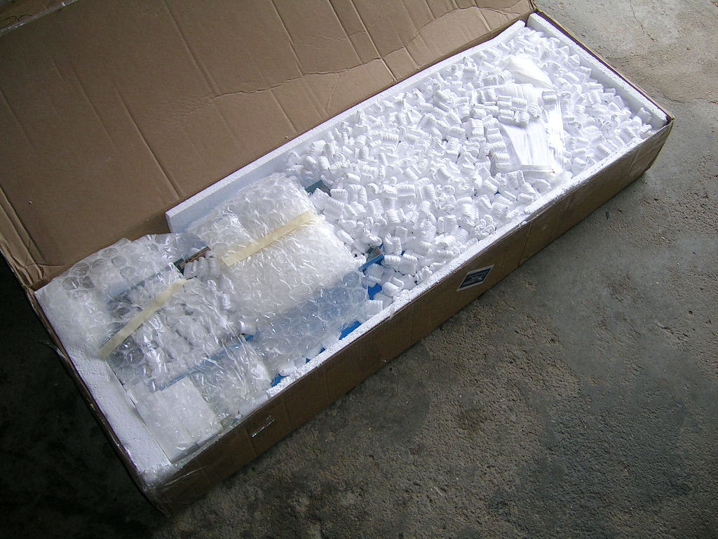
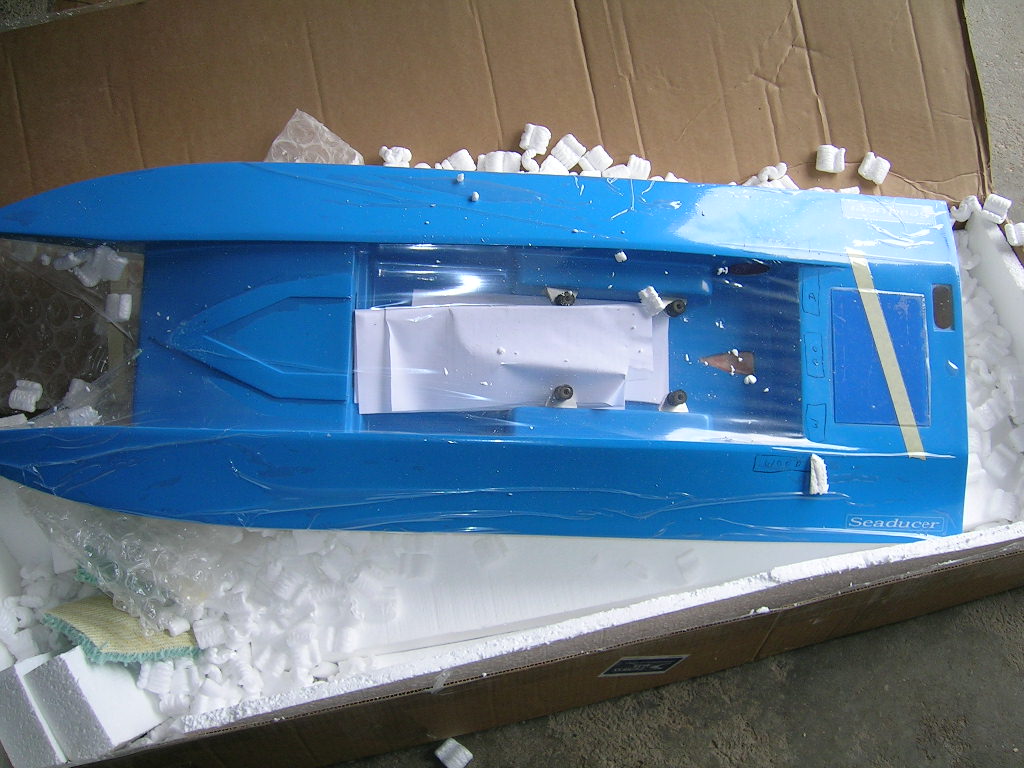
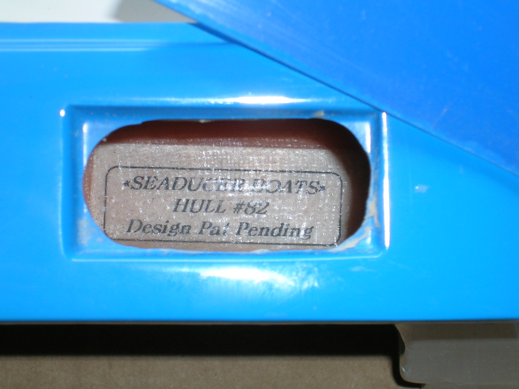
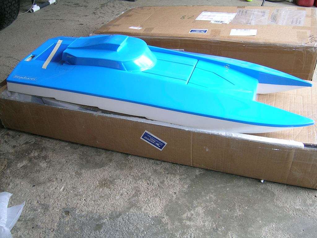
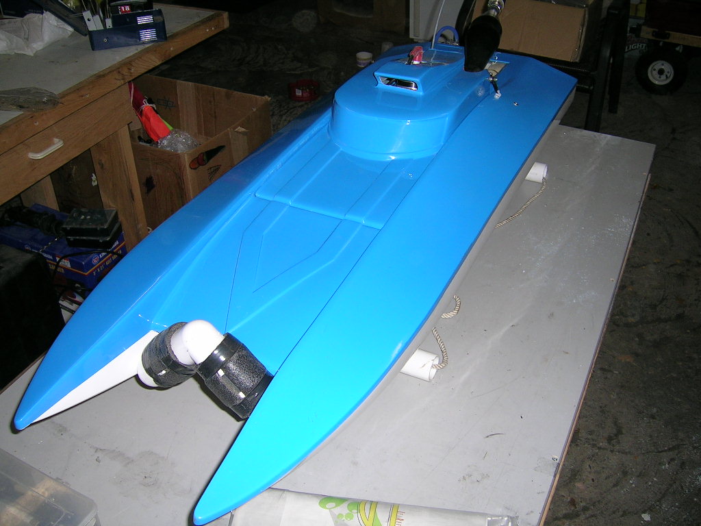
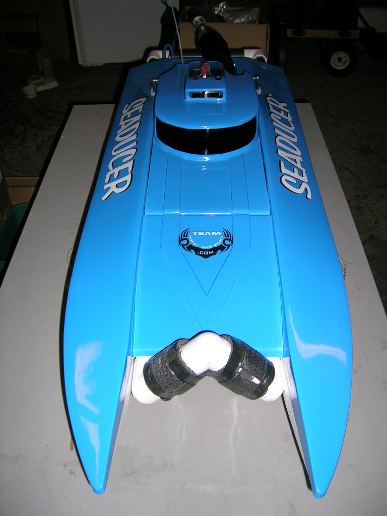
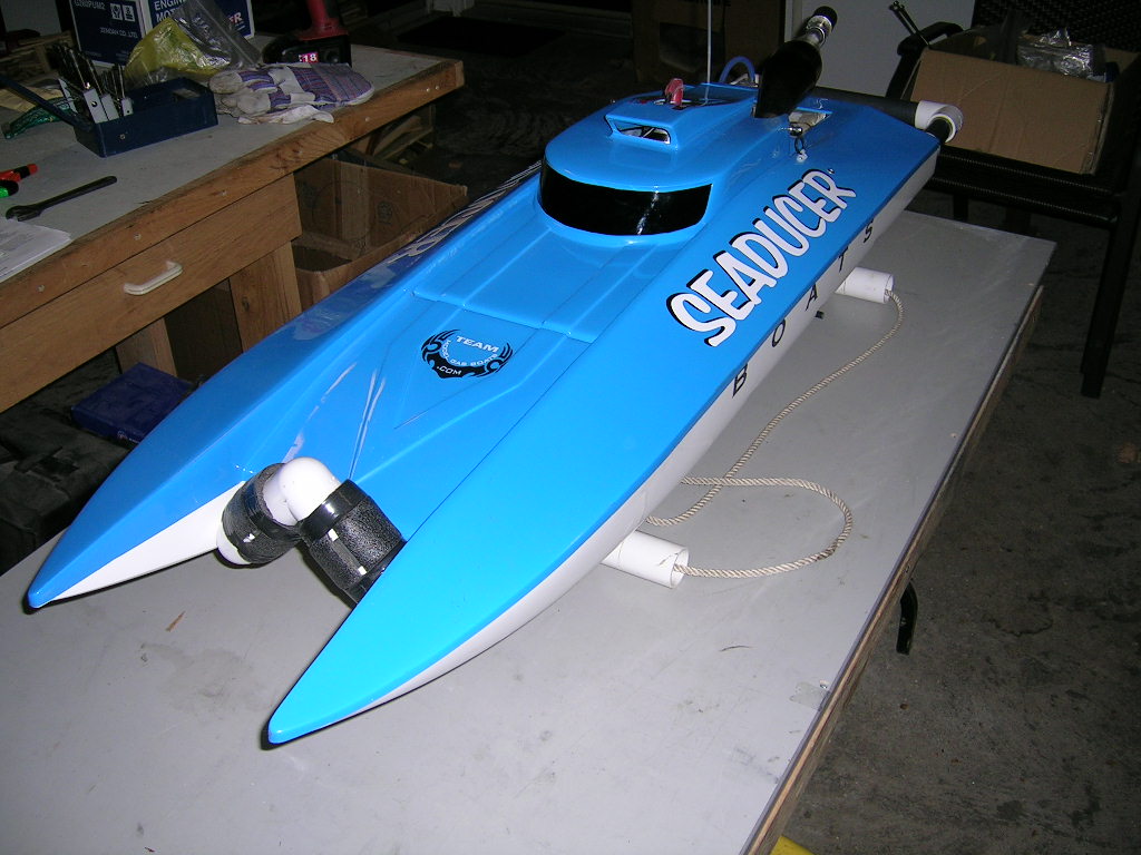
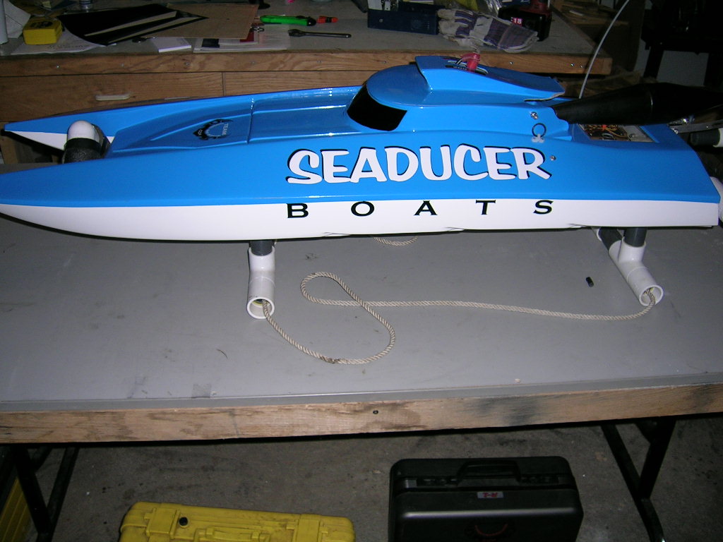
The hull is a shoebox design (which means that the top half overlaps the bottom half when the two are joined. It is made of polyester fiberglass with carbon fiber reinforcement in strategic areas. Each one is serial numbered by Seaducer Boats for proof of authenticity. The hull is 45 inches long and 16 inches wide. It has many innovative design features including a gelcoat finished engine bay, a built-in radio box, a preformed stuffing tube exit and pre-installed floatation and engine mount brackets. All this makes for a very high quality racer that is fast and easy to assemble.
Assembly
It is strongly recommended that you purchase the hardware kit and motor mounts from Seaducer boats to make your build easier and successful.
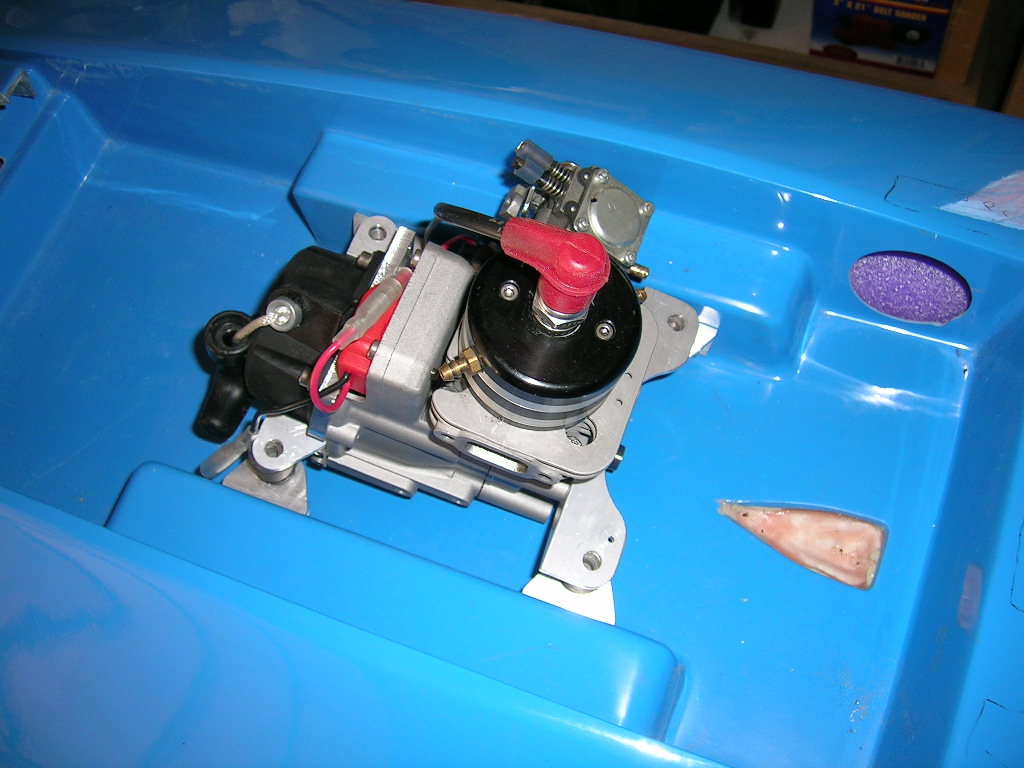
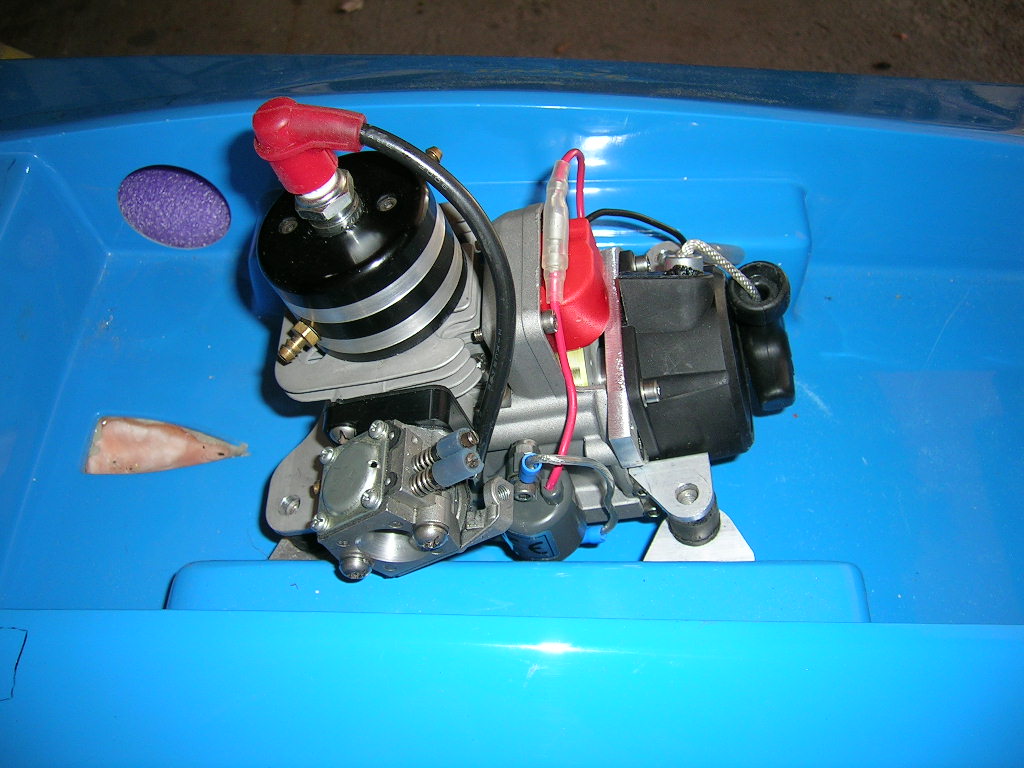
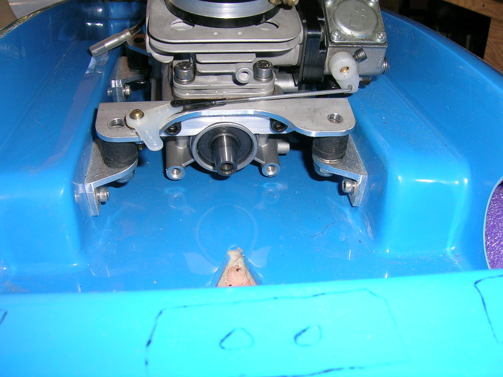
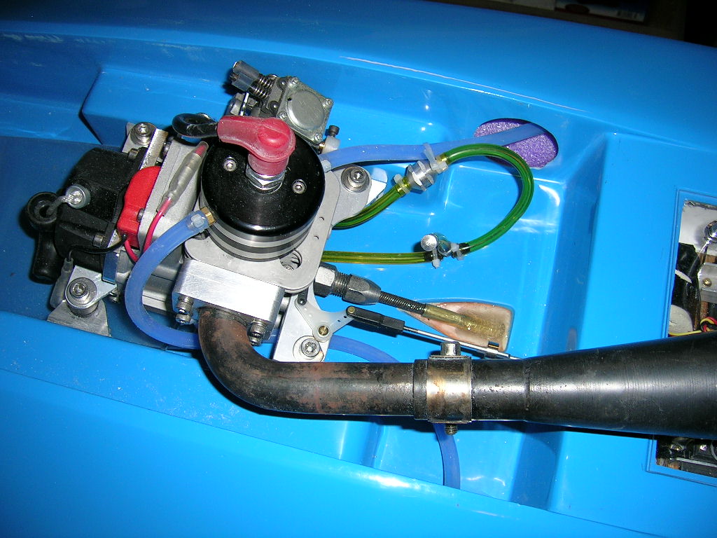
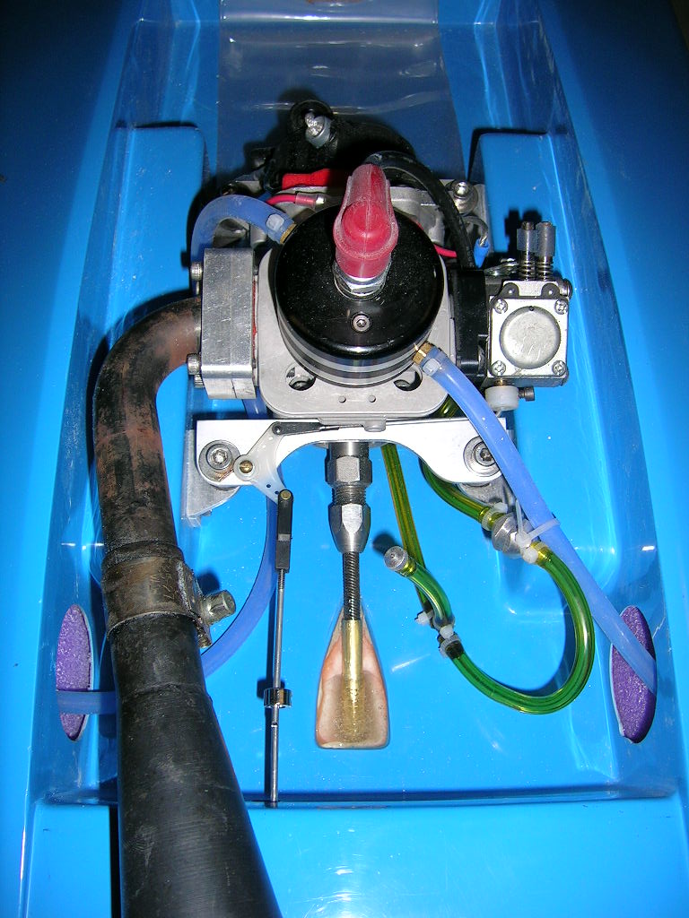
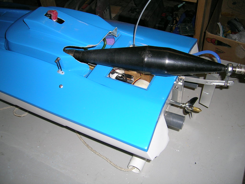
Here are some pictures of the assembly of the Seaducer cat. I started by installing the motor mounts on the engine. I then mounted it into the boat. This is as simple as dropping the engine into place on the pre-installed brackets and securing it with the included stainless steel screws and washers. This is a major time saver and there is no guessing. You know the engine is where is it supposed to be and at the correct angle.
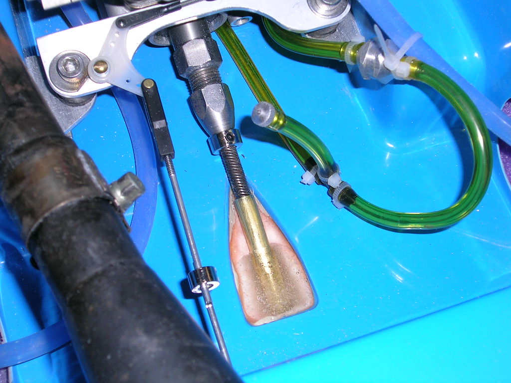
You will also have to purchase or make a throttle linkage setup as it is not included with the motor mount kit. You can see how I did mine in the picture below.
Next I installed the gas bag. There is a lot of room in front of the engine in this newer version Seaducer cat. You can fit just 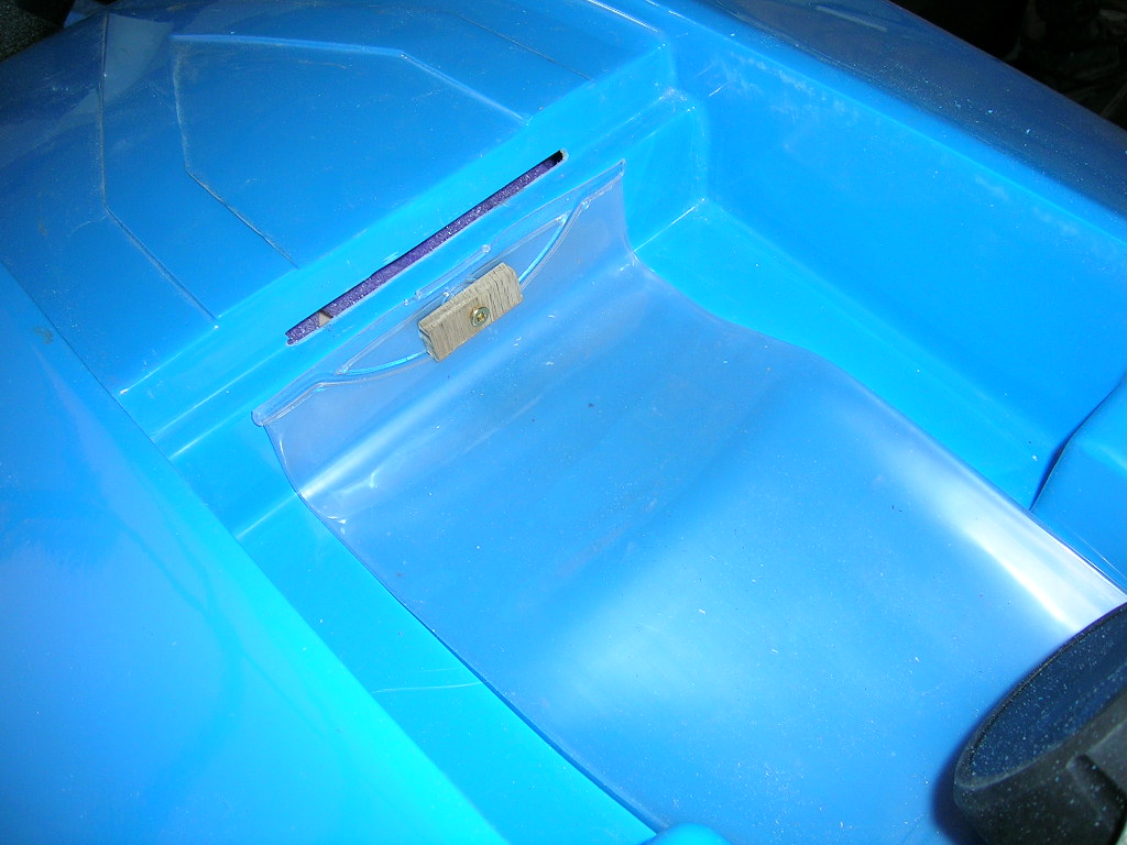
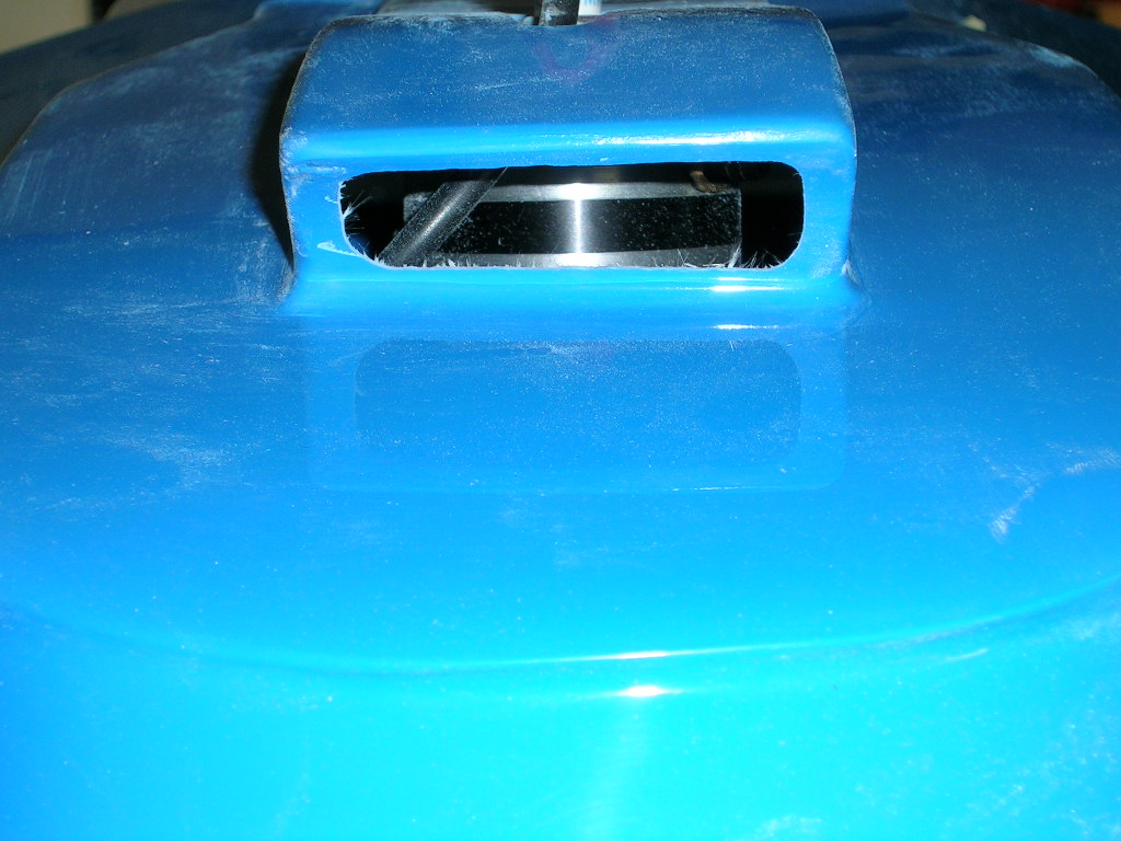
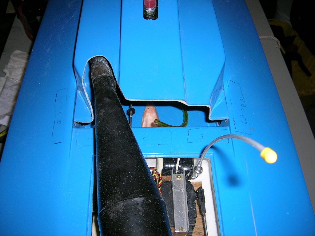
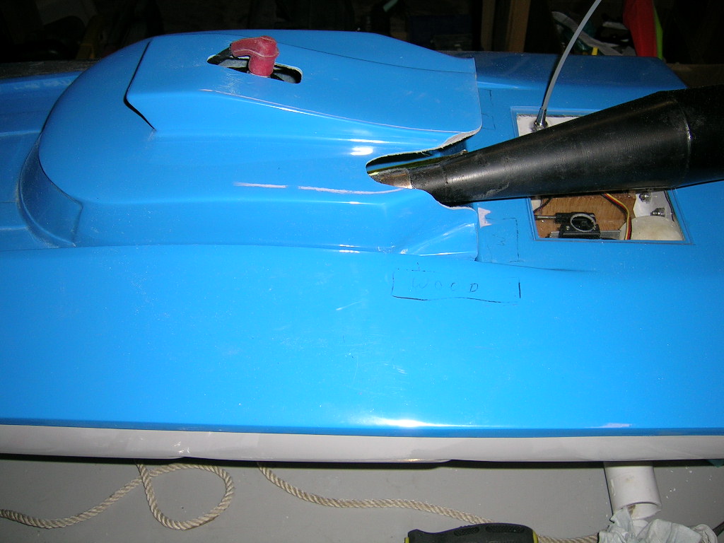
I cut out the air scoop in the cowl and test fitted. In order for the cowl to sit into place, you will have to cut out an elongated hole in the top of the air scoop where the spark plug and wire will protrude.
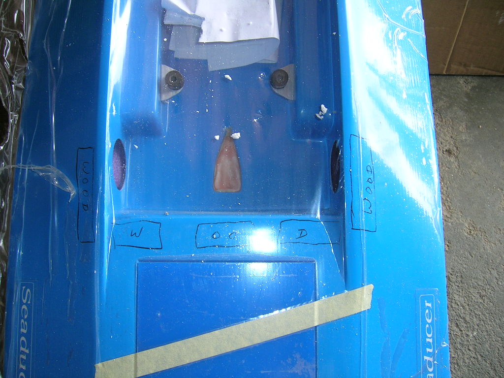
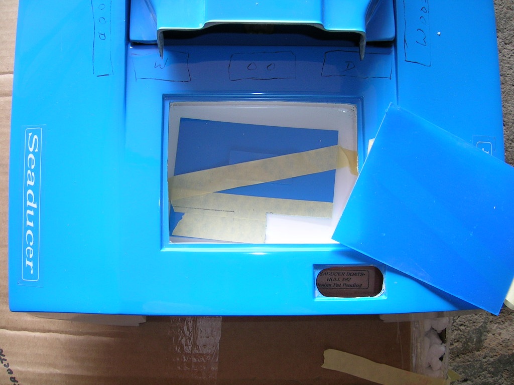
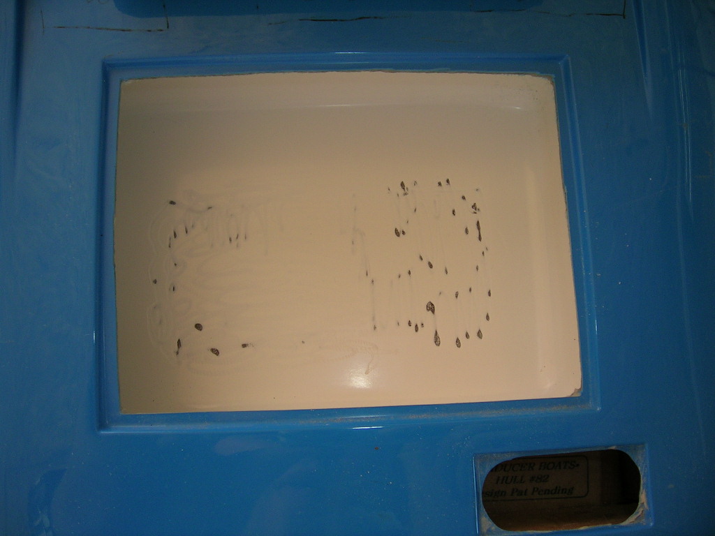
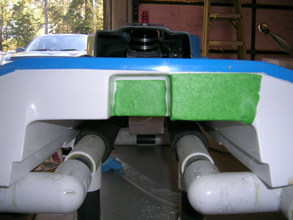
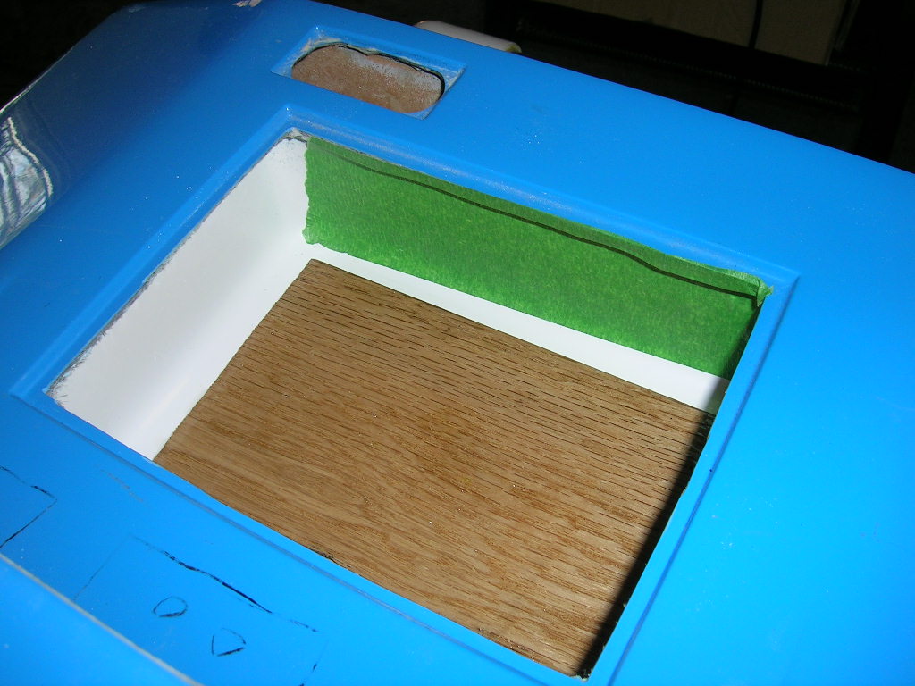
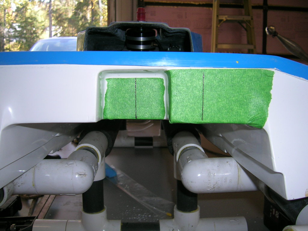
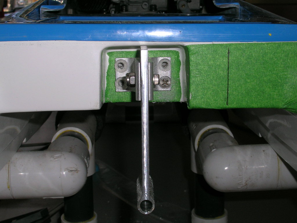
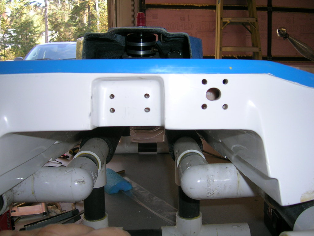
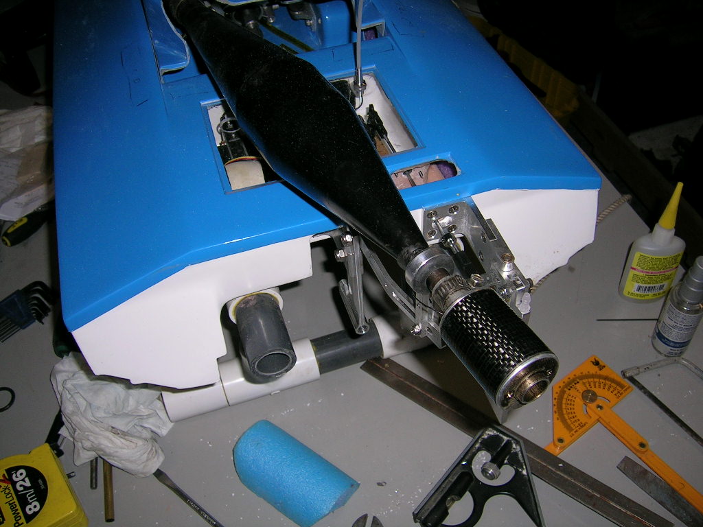
I then proceeded to tape up the transom and the inside of the radio box where I would be drilling for the transom hardware. This boat is quite different than what most of us are used to when it comes to installing the hardware and setting up the radio box. Since the radio box is integrated in the hull, some things must be done differently than usual.
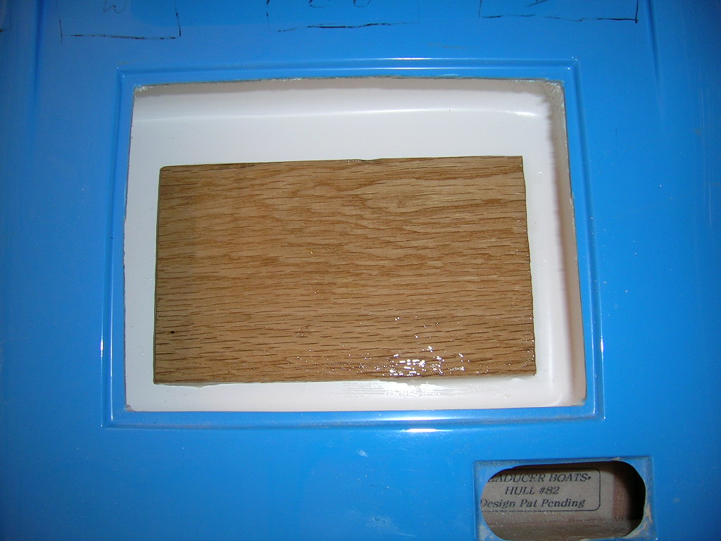
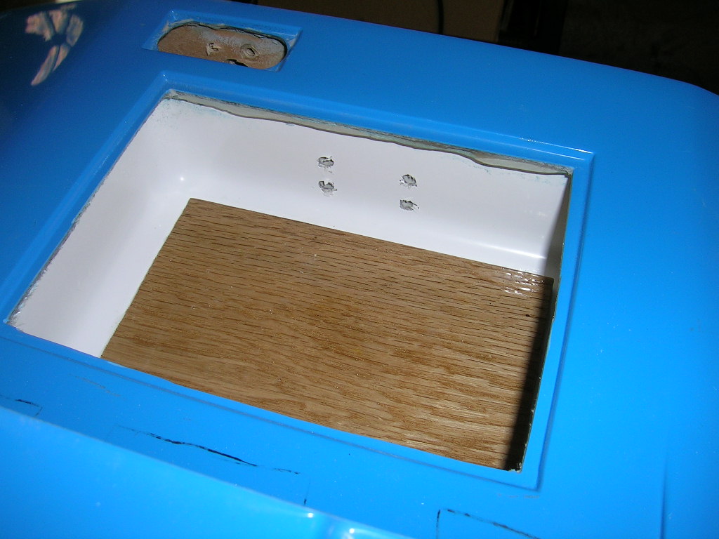
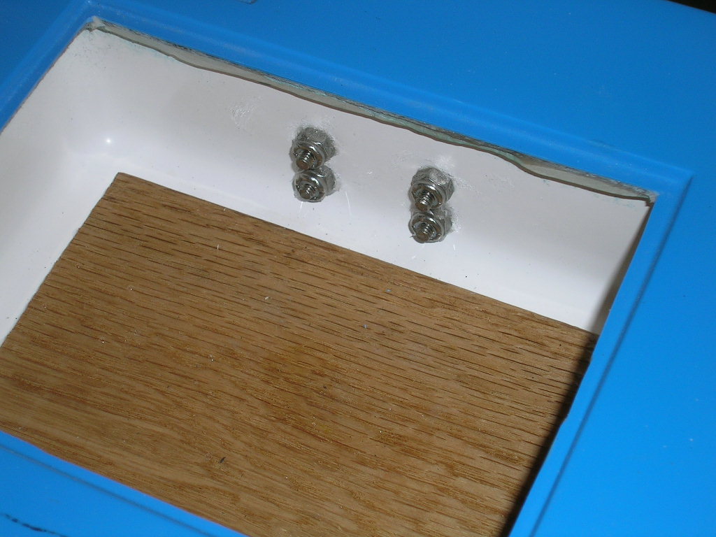
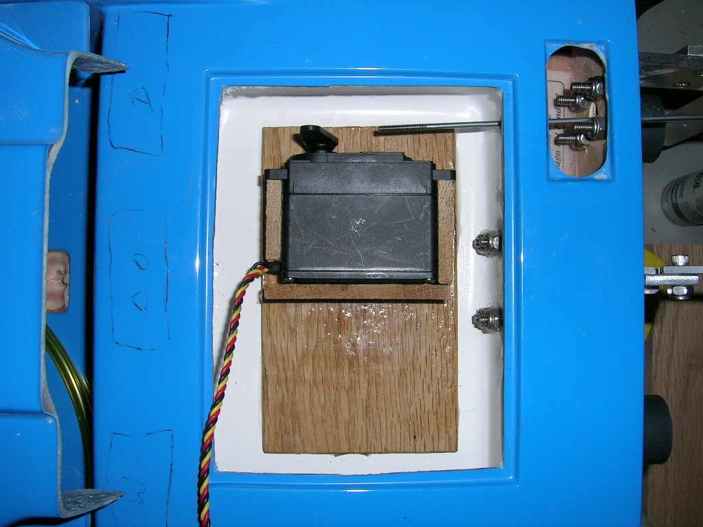
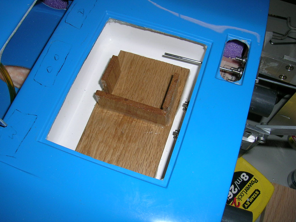
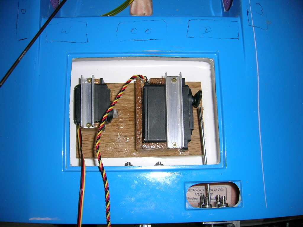
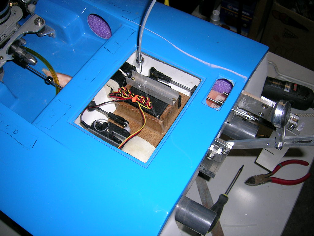
Remember to glue in a piece of 1/4" wood in the bottom of the box so that you have something to screw your servo mounts into. The bottom of the box on this hull is NOT lined with wood, so you have to do it. You should roughen up the surface on the bottom of the box so the glue will hold better. Clean it thoroughly with acetone and glue in your 1/4" wood. I used a piece of solid oak and 30 minute epoxy. The same epoxy was used to seal the piece of oak entirely to waterproof it.
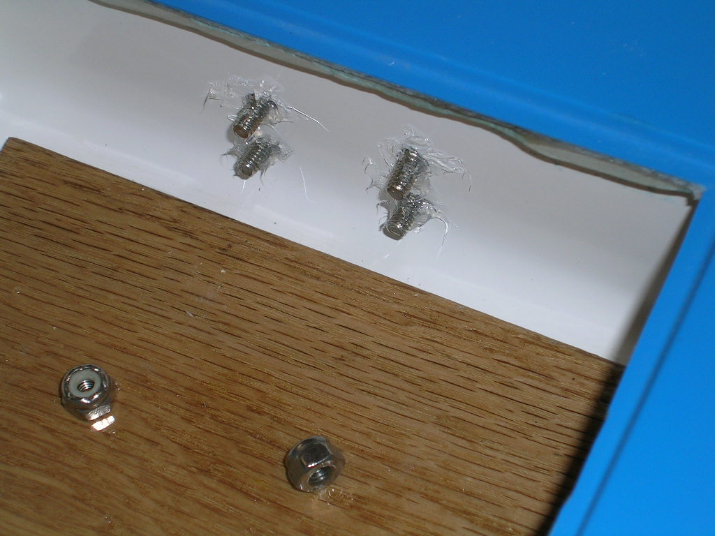
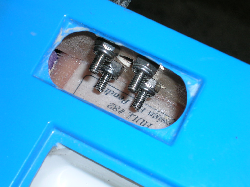
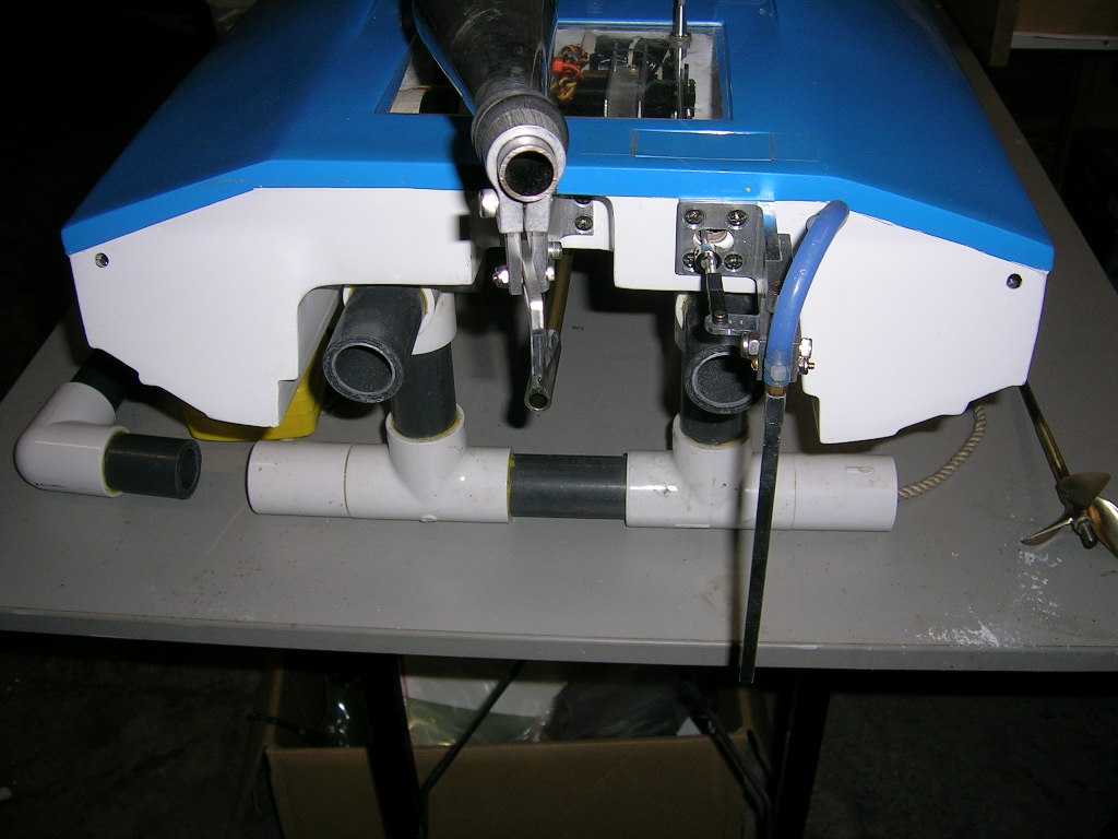
The first thing you will notice is that you cannot install the pushrod seals on the outside of the radio box. Well, I suppose one could, but it is a lot easier to mount them from the inside of the box! Another thing is when drilling for the strut, you will drill right into the radio box! The nuts for the strut bracket bolt are actually inside the radio box. The reason for this is that the strut mounts into a recessed area of the transom. The strut blade is notched to clear the top of this recess when mounted. This was a first for me as I am certain it will be for many others.
It takes a little bit of getting used to the idea of working with this integrated radio box, but honestly it works out well plus you don't have to spend time securing the box in the hull, it's already done for you!
So here goes!
After marking the transom for the hull center line (C/L) and rudder line according to the instructions I drilled the holes for the strut bracket. Make sure you position the strut brackets so that the bottom holes will clear the bottom of the radio box so you can get the nuts in. The bottom of the radio box is about 3/8" above the bottom of the tunnel area. I used some silicone sealant on the inside of the radio box where the strut bolts go through before installing the lock nuts.
While the tape is still on the transom, now is also a good time to drill for the rudder bracket. To install the lock nuts for the rudder bolts you have to go in through the small access hole between the transom and the radio box. A pair of Visegrip needle nose pliers comes in really handy for this. A small piece of pre-cut fiberglass is supplied to serve as a cover for this access hole. It is secured using radio box tape.
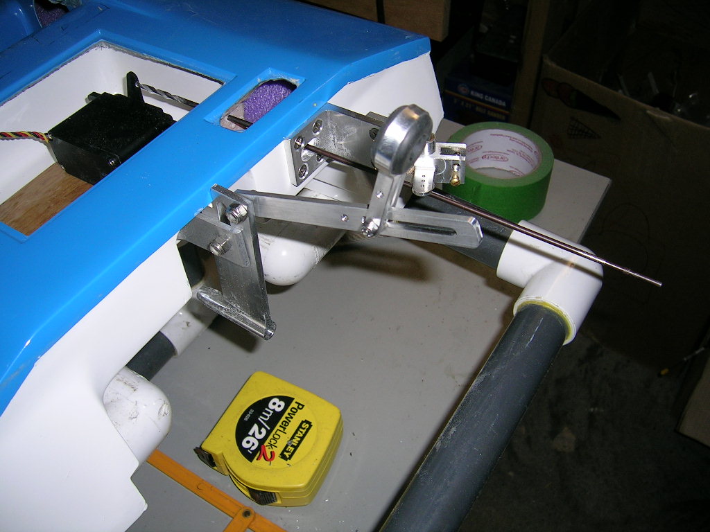
With the strut mounted you can install the tuned pipe bracket. I mounted it to the strut blade.
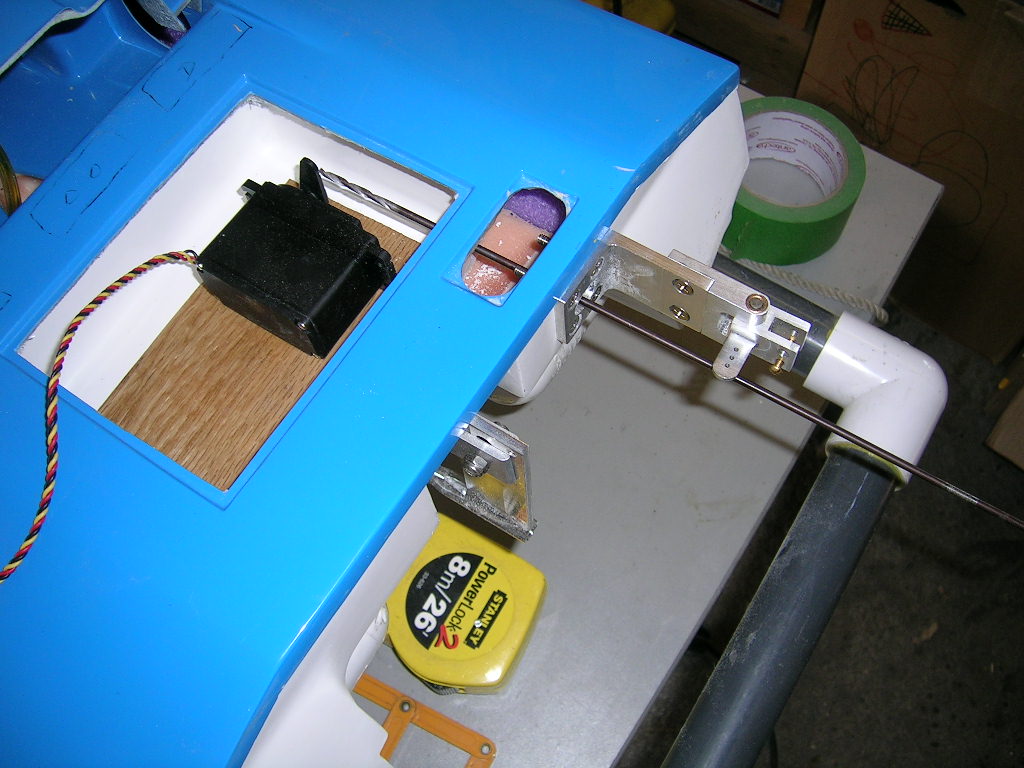
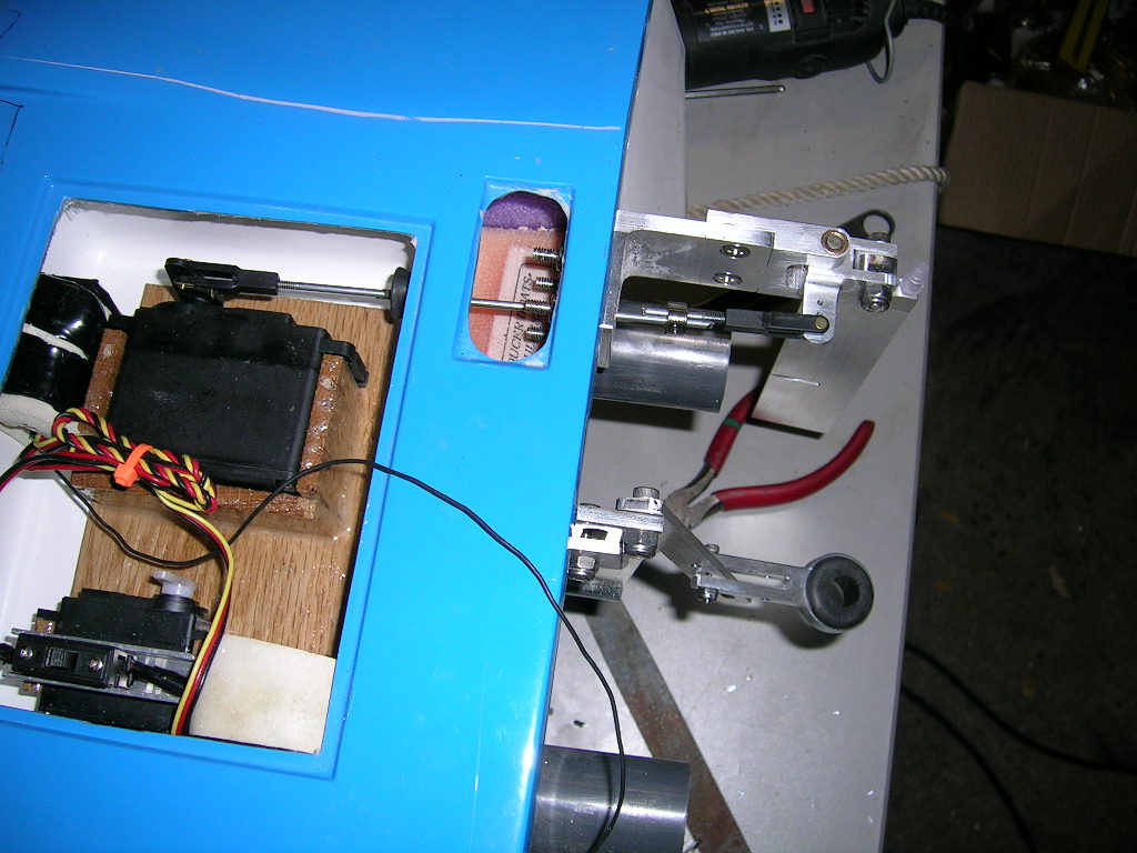
Time to drill for the control linkages. I use a 12" long 1/8" diameter drill bit for the pilot holes. It is easier to check alignment of everything with this long drill bit and get the pilot holes right. I then open up the holes with a Dremel and install the pushrods and pushrod seals.
It is worth mentioning here that in order to get perfect alignment between the rudder servo and the rudder control horn, you should use a heavy duty ball link on the rudder end. I did it using heavy duty locking clevises (since that's what I always use) and the horizontal alignment was a little bit off. I managed to work around this because of the fact that I use two-piece pushrods joined with a collar, but if you want to use a one piece pushrod and not have to bend it use the ball link at the rudder end. Mount it so the ball end is on the underside of the horn. You can see examples of these in the supplied instructions.
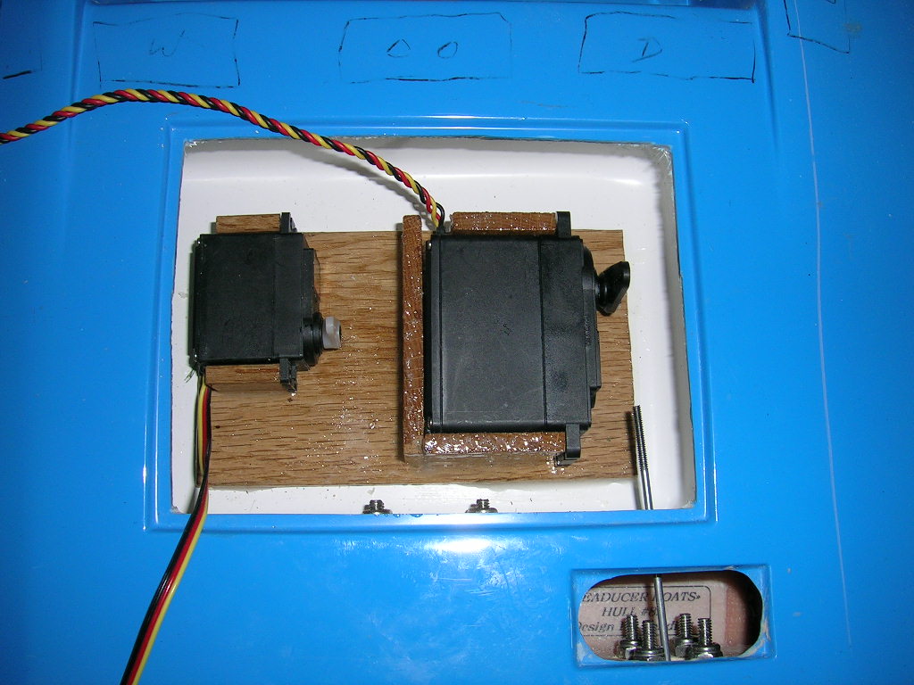
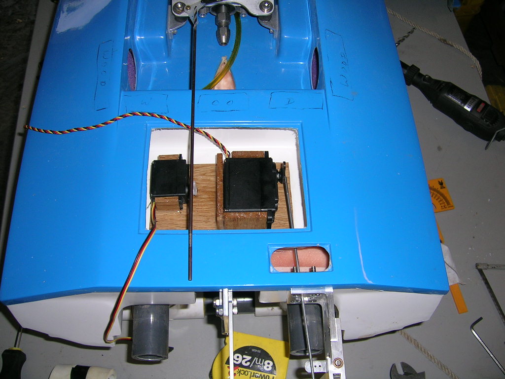
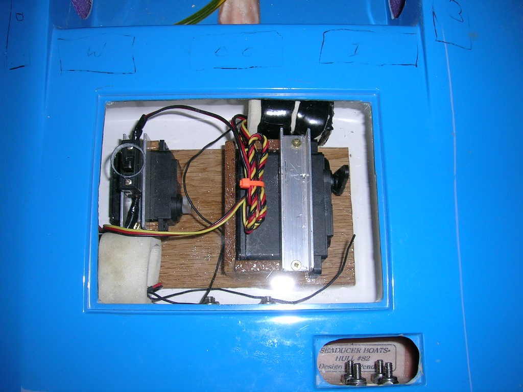
To secure the servos in the radio box I used pieces of oak epoxied into place to cradle the servos. To prevent any further movement of the servos a piece of small aluminum channel is placed over them and screwed into the pieces of oak using small screws.
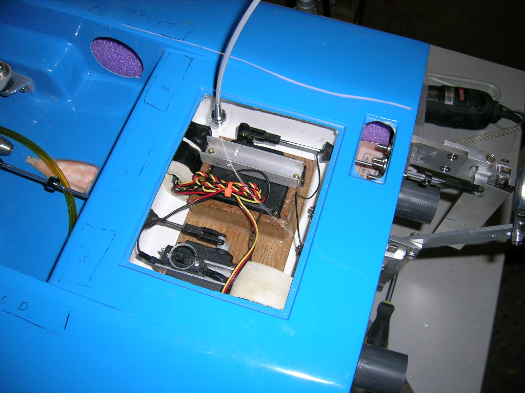
The throttle servo and pushrod installation is basically the same as for the rudder. The pushrod seals I use are from Bru-Line. They are easy to install with only 2 small stainless steel screws and feature and aluminum flange that holds the rubber boot tightly against the box for a positive seal. A dab of silicone sealant on the screws provides added insurance against leaking at the screws. Very easy to use and replacement boots are available separately.
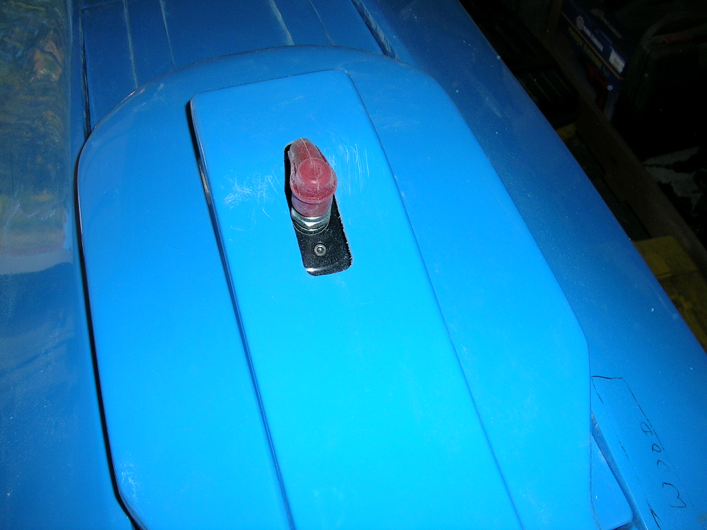
The aluminum channel I used to secure the throttle servo also doubles as a switch mount. I drilled the radio box cover to have access to the switch without removing the cover. This hole is sealed with the same radio box tape used to seal the cover to the box. The antenna is also mounted in the radio box cover. I like to use a small Oring on the antenna mount to help it seal better against the cover. A little bit of silicone sealant can also be used instead.
At this point I installed a tuned pipe on the engine and trimmed the cowl for a good fit.
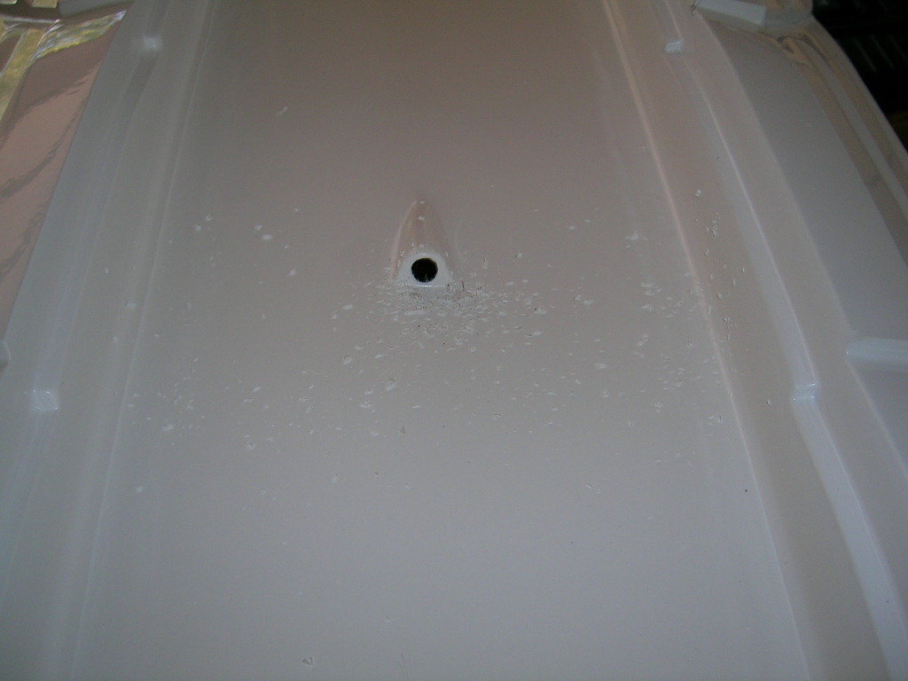
The stuffing tube installation is made very easy in this boat. You will notice a small cavity in the bottom of the tunnel just behind the motor (between the motor and the radio box). This is where the stuffing tube will exit the hull. Simply drill the back of this cavity with a 5/16" drill bit. You might want to start with a small pilot hole, making sure it’s centered. You can do this from the inside of the boat if your engine isn't already mounted. If it is, you can do it from under the boat. Either way it's very easy. Once the hole is done, mount the engine if it isn't already and run your 5/16" stuffing tube from the strut to the engine, leaving a gap (3/4" - 1") between it and the engine collet. If you want the stuffing tube to be removable, drill the hole 11/32" instead and use a short length of 11/32" brass tubing as a sleeve over your stuffing tube for the length where it crosses the hull bottom. About 3 - 4" long will suffice. Bend the stuffing tube for good alignment with the motor and run it all the way into the strut. Install a flex cable from the strut into the engine collet and make sure everything lines up correctly. When you are satisfied with the positioning, use a bit of C.A. to secure the stuffing tube (or 11/32" sleeve) in place. Mix up some epoxy and pour it into the cavity around the stuffing tube or sleeve. It is a good idea to thoroughly clean the area with acetone prior to gluing. Also, sand the brass tubing with some coarse sand paper to give the epoxy something to grab onto.
The final steps include running the gas lines from the gas bag to the engine. I set it up with a "T" fitting to have a fill line and installed a gas filter between the "T" and the carburetor. The water line is run through the inside of the starboard sponson up to the engine bay. This is explained in the instructions and is easy to do. The water outlet is easy to install on the port side through the hull cut-out in the engine bay.
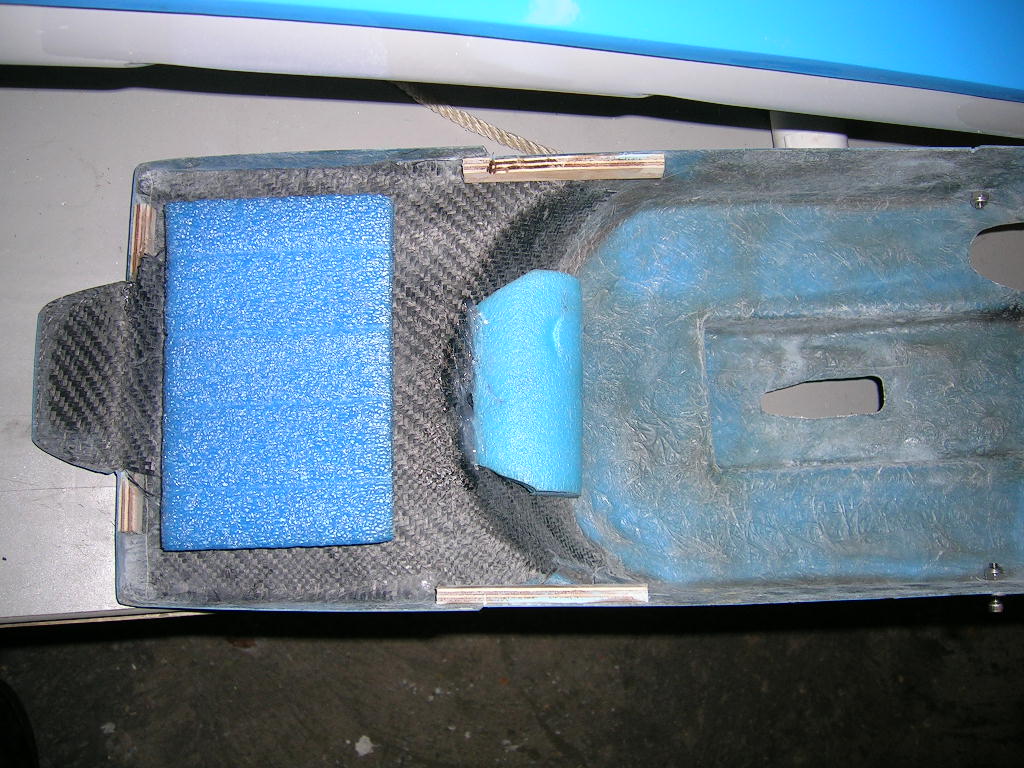
The cowl features a built-in front tab and the deck of the hull is already slotted to accept this. All you have to do is decide what to use to for hold-downs at the back of the cowl. I used Orings. You will also notice that the entire front portion of the cowl is reinforced with carbon fiber! Remember to install floatation for the cowl. For the hull itself you do not have to bother, this is another thing pre-installed by Seaducer Boats!
You should also drill some drain holes in the back of the sponsons so that you can drain water out in the event of a blow over.
A few graphics and we're ready to go...
Pre-run setup
There really isn't much to do to get your Seaducer cat ready for the pond. The boat is supplied with a strut adjustment kit which is simply 3 pieces of ply wood. Set the boat on a flat surface (this is important) and the two 3/8" pieces of wood under each sponson at 22 inches from the transom. Place the 1/8" piece under the strut and set the strut flat against this piece. Tighten the strut screws. This sets the strut with about 2-2 degrees of positive trim and at the height recommended.
At the Lake
The first time I ran the Seaducer cat the water conditions really were not what this cat was designed for. The lake was like a mirror and the boat ran extremely wet. I ended up running the strut as high as I could get it and with a lot of positive trim. I simply could not get the boat to break loose. I did manage to get it to run fairly well with a low pitch 2 blade prop, but I knew this wasn't the ticket. I packed it in for the day.
Back at the shop, I modified the strut blade a little bit. I slotted the top of the blade enough to allow for the strut to be set about 5/8" above the sponson bottoms. I ended up mounting the strut 1/2" above the sponsons with about 2 degrees of positive angle. The propeller I used was a 6717/3 (380) from Propworks. Normally I would stick with the manufacturer's recommended settings, and I always suggest this, but in this case I did not have the propeller that Seaducer normally sell for this boat and the water conditions were not really what this boat was intended for, so I had to compromise.
I headed back to the lake and this time the boat ran better, but still wasn't like I wanted it to be although the water conditions were better. There was more chop, and trust me folks, this boat loves chop! It was after all designed for heat racing!
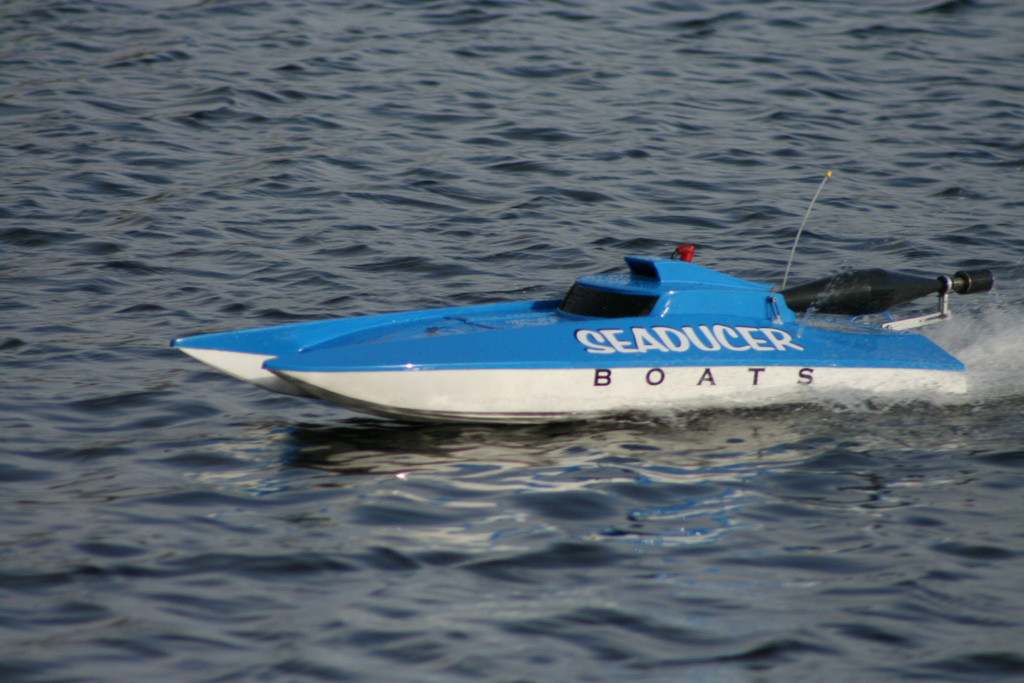
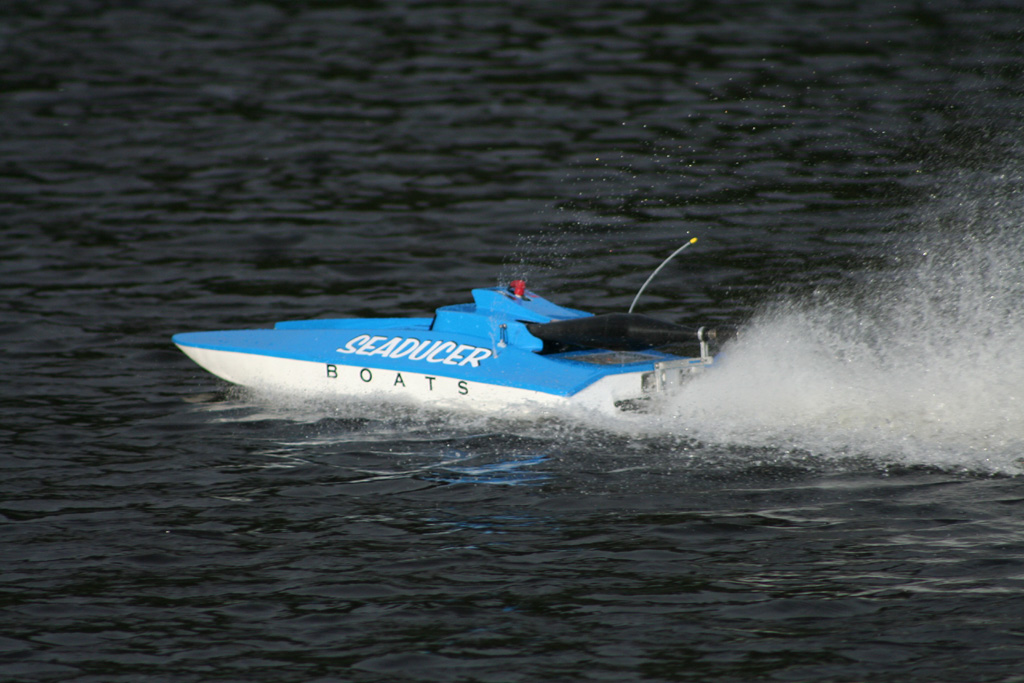
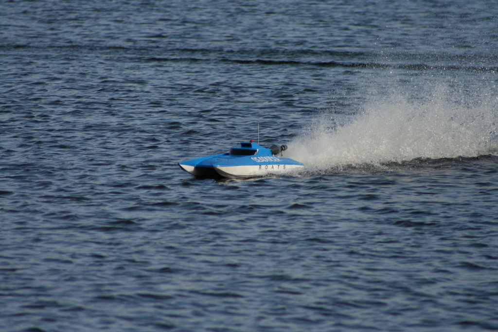
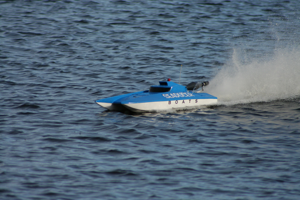
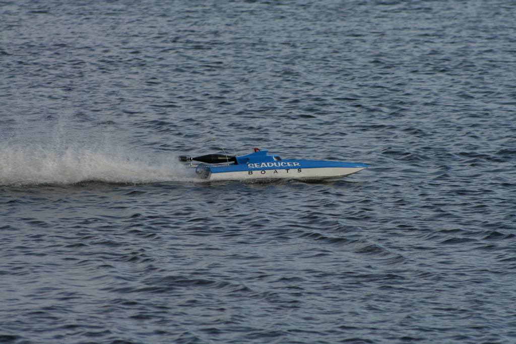
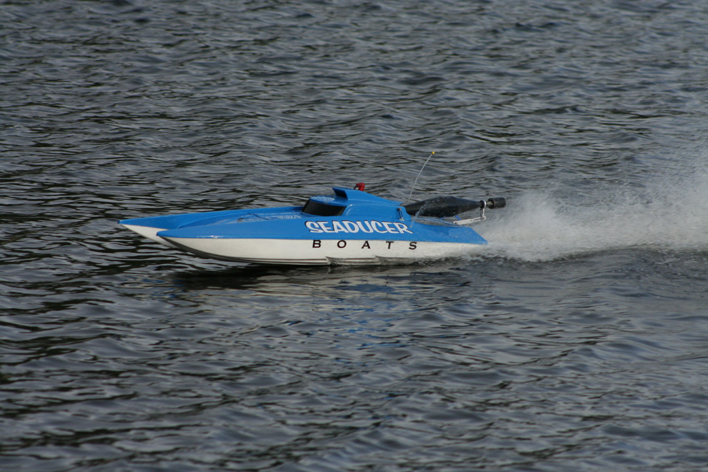
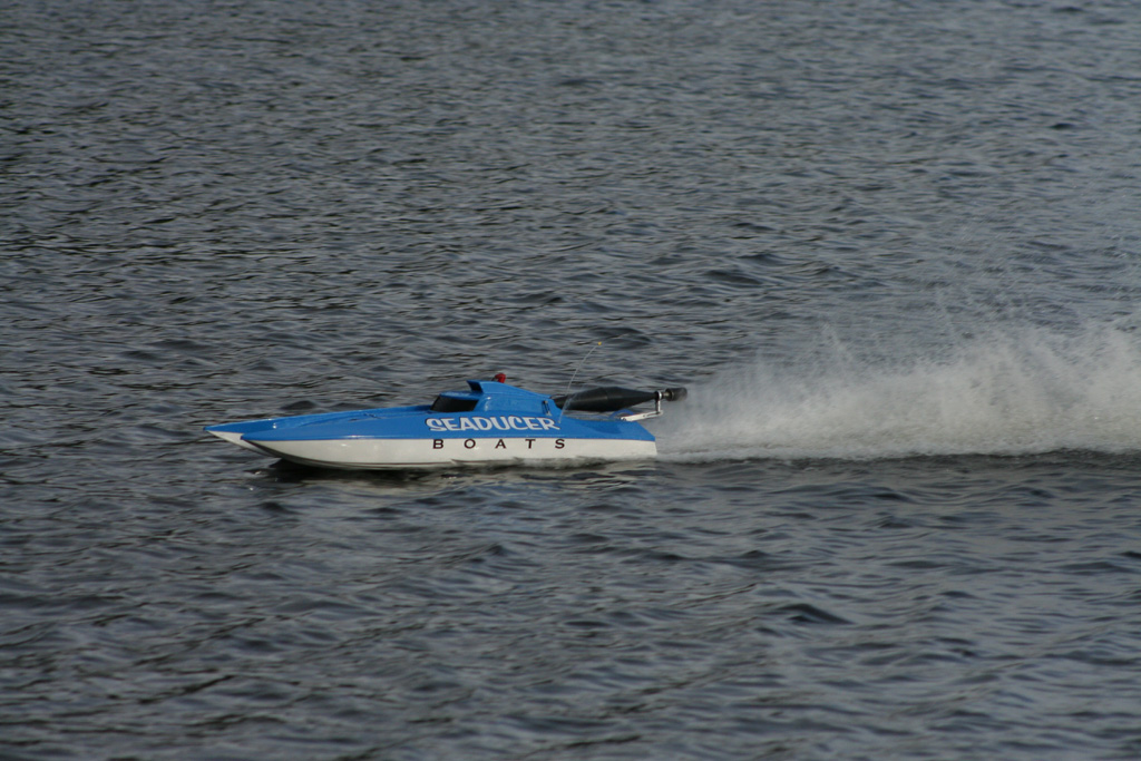
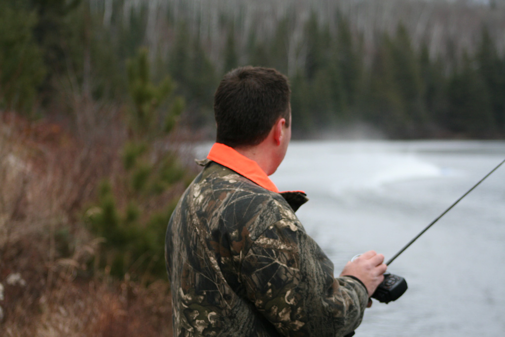
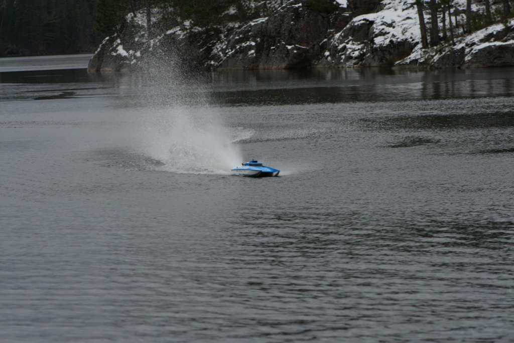
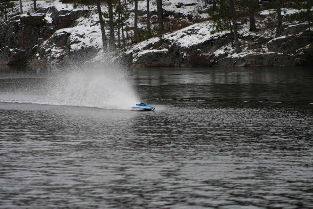
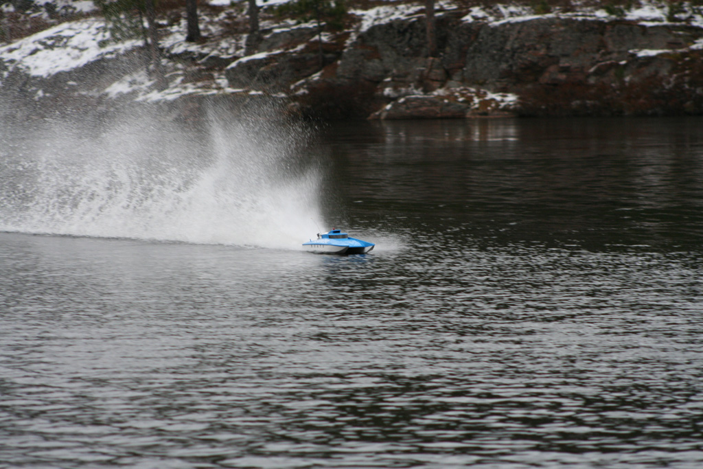
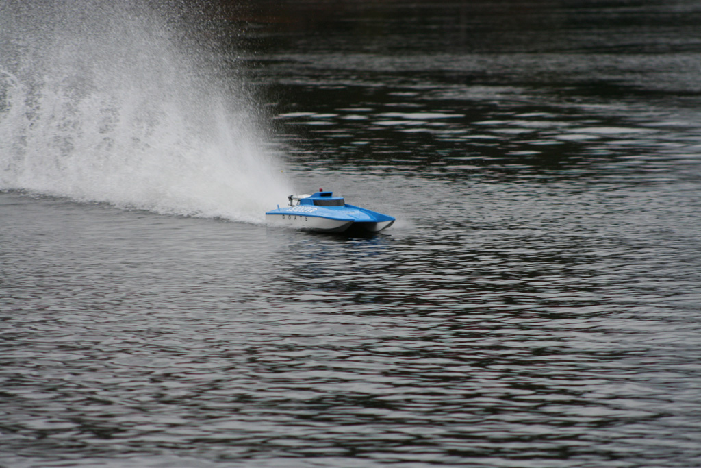
The third time out I decided to pull out my motor and replace it with a motor from CC Racing Engines with a Powermaster pipe. The added power of the CC motor really brought the boat to life! Although I was limited in space because of parts of the lake starting to freeze up, I could still get a good feeling of how the boat performed. It was fast, cornered strong and drove like a true race boat! I also let my friend Pat drive the boat for a while to see what he thought and to give me an opportunity to take some pictures. This was his first time driving a radio controlled boat....looks like he had a blast!
Here a some action shots...

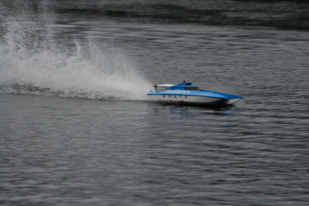
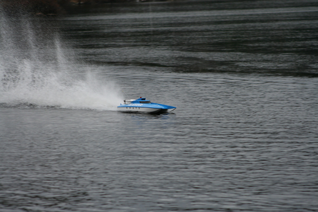
Here is a video clip...
Things I liked...
- sturdy construction
- enclosed engine bay, easy to clean - all gel coat finish
- pre-installed floatation
- cowl tab - deck slot pre-cut, carbon fiber reinforced cowl
- pre-installed motor mount brackets
- integrated radio box
- stuffing tube exit pre-formed in hull bottom
- high quality motor mounts
- hardware kit includes pipe mount and antenna
- great performance, fast and stable..."sticky" design...makes it perfect for heat racing in heavy traffic and rough water conditions
Things I didn't like...
- no throttle linkage included in kit
- motor mounts do not allow for starboard side starter mounting (personal preference only)
Final thoughts...
The Seaducer cat is a great boat that is very well complimented with the available hardware kit. Seaducer Boats have done all the most difficult parts of the setup for you when you receive the kit. The quality of the hull is very good. Although I would not recommend this boat as a play boat or for someone planning to run alone on a small pond, I would not hesitate to recommend it to the racers. In high traffic heat racing with rough water conditions is where this boat will shine!
Happy Boating!
* I would like to thank Chris Rupley and Mark Pittman for their assistance on this build.
Contact Information:
Seaducer Boats
Jerry Crowther
2071 NE 55 Ct
Ft. Lauderdale, Fl 33308Phone (954) 493 7387Fax (954) 772 9002
Website: www.seaducerboats.comEmail: This email address is being protected from spambots. You need JavaScript enabled to view it.


