How-to Article...Submitted by Hendrick Spoor
Learn how to make design an ultra quiet tuned pipe...
Because a fellow-boater heard about my QD silencer rebuilds ,he asked me if I could do the same with his pipe.
He bought it as a "silent pipe" , but that is measured to the USA standards. This pipe (I think a Andy Brown parabolic silent) is producing 90/92 Db(a) and that is way too much for the stricter European regulations (80/82 Db(a).
As I did earlier with the (European) CMB-Nitro .90 pipe to adapt it to Petrol/Gas-pipe, I knew that for keeping the rev's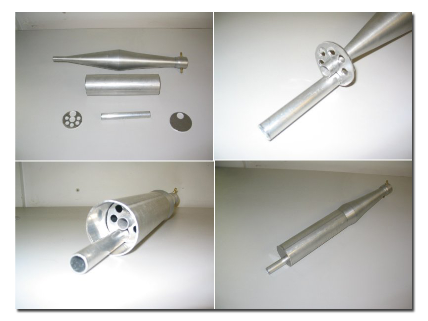 and torque you have to calculate the passageway of the gasses through the muffler quite meticulously. By trial and error we found out that a two stage muffler with 150% square-area stinger-diameter in the first stage , and 130% square-area stinger-diameter in the second stage , works the best "all" considered. That "all" is effective sound reduction and the slightest power/rev's loss.
So .... these are the calculations performed for this 'Andy Brown Parabolic-silent'.
Sorry for the metric ...... for imperial you have to use the conversion table and the square-area measure imperial-arithmetic you have to do yourself.
150% x 113 =169,5mm² / 6 x Ø 6,0mm(28,27mm² x 6)=169,62mm² square-area measure / Front-bafflepipe
130% x 113 =146,9mm² / 6 x Ø 5,6mm(24,63mm² x 6)=147,78mm² square-area measure / Aft-bafflepipe
Where Ø stands for ... drilled holes.
As you can see the 150% is actualy 169,5mm² and the 6 bore 6mm holes are giving a total of 169,62mm². In small round objects the drilled holes become bigger , so again by trial and error I found out that for Ø 6,0mm the drill has to be 5,9mm and for the Ø 5,6mm the drill has to be 5,5mm.
Now I had to go to the metalshop to buy the needed aluminum:
Aluminum-tube : 14mm x 17mm (to fit over the original stinger)
Aluminum-full : 18mm Ø ( to turn a divider between the front and aft baffle pipe)
Aluminum-tube : 52mm x 48mm ( as the outer muffler-wall - 'can')
Aluminum-full : 52mm Ø x 12mm ( to lathe the backplate)
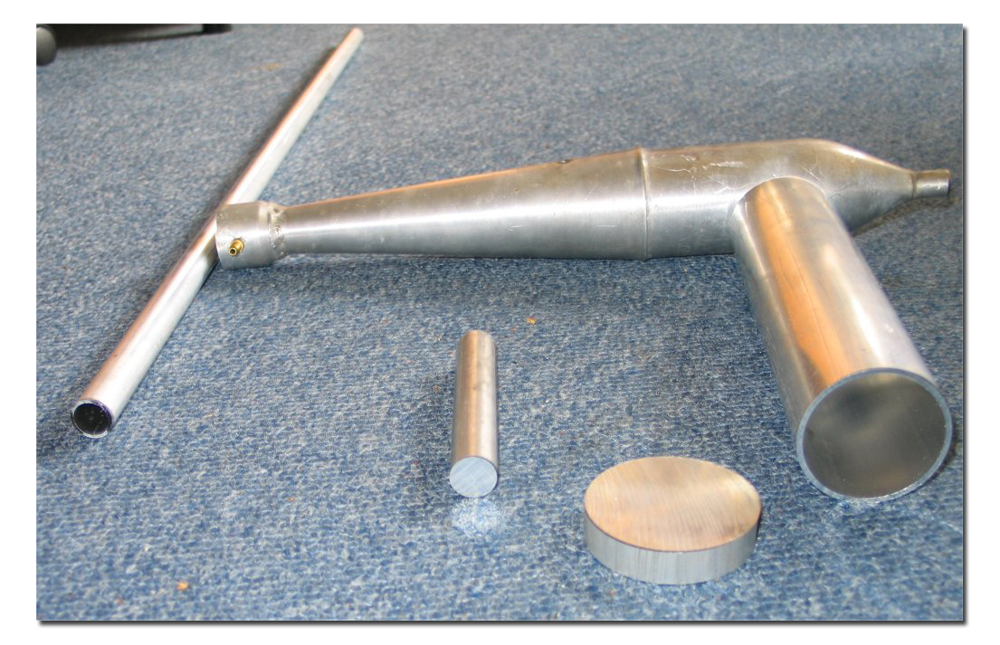 Sometimes I get lucky and find the things I need or could use in the metalshop scrap bin or in the leftovers.
So there are parts in this picture that are bigger/longer than needed.
 All parts made the right size by sawing or turning.
In the tweezer you see the divider.
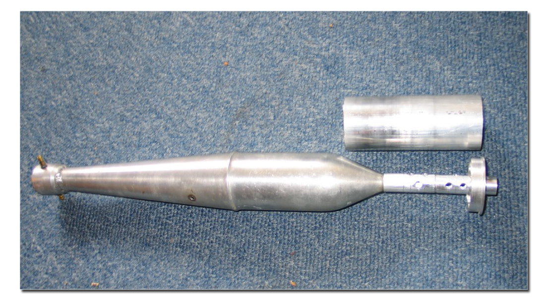 This is the view of how the internals fit within the 'can'.
120° drilling and tapping of M3 threads has to be done.
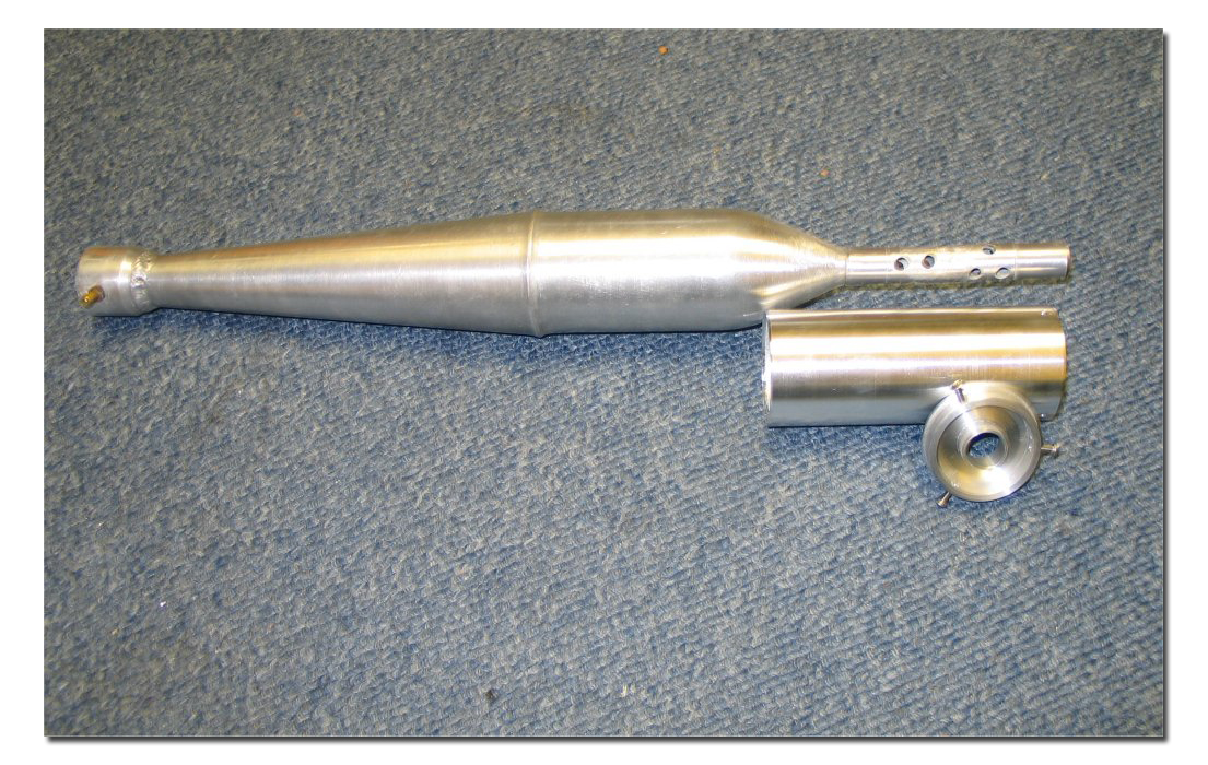 120° drilling and M3 thread-tapping done.
Also reduced the outer diameter of the 'can' on the lathe from 52 to 50 mm.
50mm is the standard European pipe-clamp size.
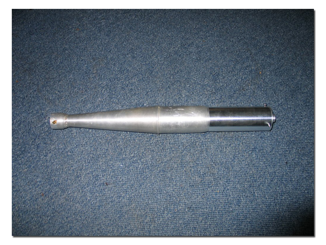 Checking the overall fit , and ready to join by hard-soldering .
The hard soldering of aluminum is tricky because the melt-down and the soldering temperature
are very close to each other .
The melting temperature of aluminum depends on the kind of aloy used ,
and is between the 585ºC and 660ºC.
The hard-soldering temperature is 570ºC and is therefore as strong as silver-solder on SS/Copper/Brass .
The strength of the joint is 16>18Kg/mm².
The materials I use and my long experience make it easier.
Marc Levac asked me to elaborate on this hard-soldering/brazing process , so here goes :
25 years ago when I was involved in oldtimer restoration (as a hobby) I came across a welder
who was doing motorcycle/car/outboard welding on gearboxes , crankcases , cylinder heads ,
and outboard-legs .
They also used that Alumiet 163 flux-powder and Vedal 460 brazing-rods.
(A brand of the Dutch VéDé-products made by Delville and sons.)
These materials are not commercially available (for private persons) ,
but the regional sales representative is kind enough to sell me their "test/evaluation-samples".
For the brazing a USA made Spitfire propane TurboTorch is used.
Recommended by that welder , because of the "spread" of the flame.
Witch is ideal for doing this home DIY soldering.
Generally we hobby-guy's do not have their Acetylene/Oxygen combo's with differend tips.
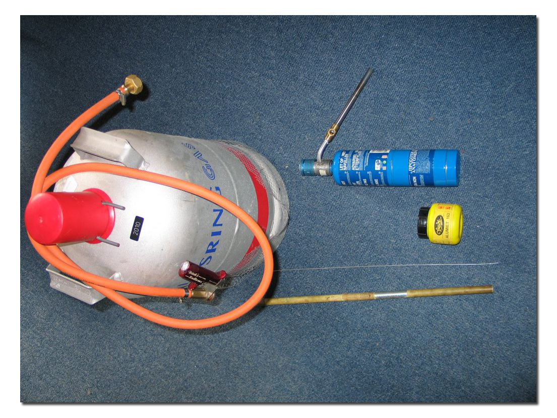 Here you see that a clone propane can is used .... the original Spitfire-TurboTorch can is red.
Also on this picture the flux and the rods and the homemade RV-propane coupler
that is used for time consuming jobs .
And hey ....I'm Dutch ... it's also much cheaper using the RV-propane.
And this is the way to do the job :
I took a rod that slips into the pipe and clamped it (slanted-upwards) in a workbench-vice.
Slipped into a leather working glove with my left hand.
(That's to be able to turn the pipe without getting burned.)
Put the pipe on the rod , opend the flux , light the torch.
First heating the rod enough to stick it into the fluxpowder , so this powder will stick to the rod ,
and then in circular pattern heating the area of the joint to be made.
As to determine the right soldering temperature , a little piece of the rod is forced onto the joint.
As soon as that forced piece starts to 'run' , you can go ahead .
Alway's keeping the right temperature by going nearer or withdrawing with the flame.
This is a trick that can be learned only by alot of practice.
Yes .. the trial and error method again, and believe me, I practiced and ruined much on scraps.
(and yes ....on actual parts too ![]() )
)
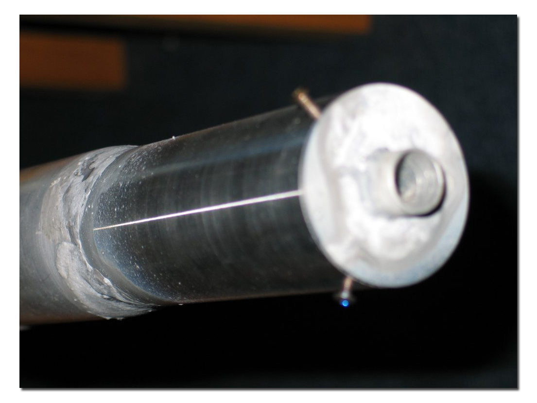 Hard soldering done.
You see the joining of the 'can' to the pipe and the muffler-stinger to the backplate.
What you don't see is the joining of the front and aft baffle pipes with the divider.
But that's been done! ![]()
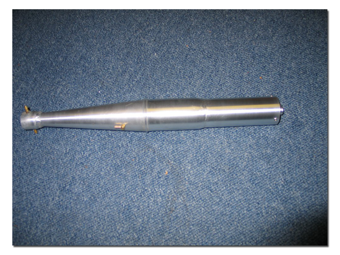 View after filing / Dremel'ing / sanding.
 Same here .... but using the lathe.
 Ready for assembling .
As you can see, for cleaning purposes you can take it apart.
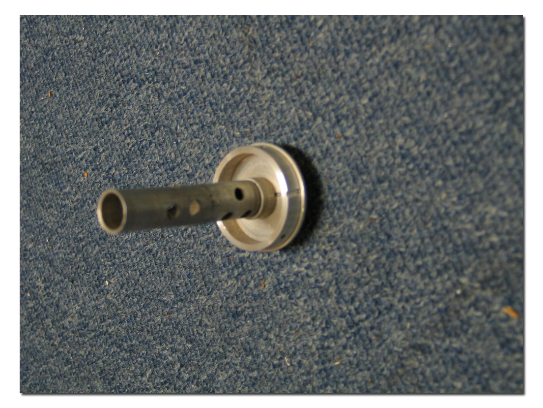 But as I dislike cleaning,
I made an oil groove and bore in the outer ring of the backplate
and a bore in the inner-ring out into the muffler-stinger.
After racing you just put the pipe on it's 'back'.
If the noise is still not correct Stainless Steel kitchen scrub can be added.
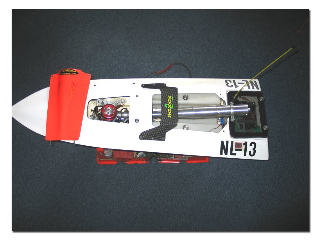 Just for display reason: pipe mounted on my FSR-V15 competition racing hull.
And please don't think my hobby room is so clean that it has carpet as you see on the previous pictures...
just to avoid flashback if camera wants to flash the pictures are taken on the floor of my home-office.
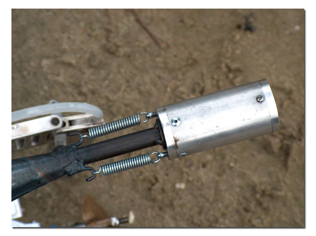
My hobbyroom (in cleaned-up version - ha ha ) can be seen here:
 This article started with the question from a fellow boater
if I could do the QD-silencer rebuild-trick to his pipe.
Now I've to fill you in about that too ?
Ok ........ here it comes.
This is an original QD-silencer after rebuilding it .
Notice the little M3 flathead hex-bolts instead of the rivets.
The rest of the story.
I 'dremel'd' away the 'aft' rivets and cut M3 in it .
After opening the content of that thing was ... a tiny roll of 'chickenwire'
and some filthy antinoise-Wool filled with oil.
That muffler was 71,3mm long inside ..the baffle dish is 30mm measured from the front-outside.
The pipe stinger sticks 13mm into the muffler.
At first I did the flow calculations @ 150% stinger Ø .(11mm)
Both for the baffle dish and the baffle tube.
Measuring today 84Db(a) ... with NO loss at all ( No torque NO top).
I could make the flow of the drilled tube = 2nd stage @130% , but the owner is satisfied already .
You can't see it well on the next picture but the 'baffle plate' is parabolic (like a satellite dish antenna).
Calculations ;(pR²)
Stinger = 11mm square/area measure = 95mm²
130% of 95 = 123,5mm²
150% of 95 = 142,5mm²
Muffler inner-diam = 36,5mm square/area measure = 1046mm²
The first stage baffleplate/dish = 34,0mm diam. square/area measure = 907mm²
1046 - 907 = 139mm² close enough to the needed 142,5mm²
The second stage aluminum tube is 12x14mm cut down one side to press-fit the backplate and to be soldered later on.
The first-stage dish is also alu-soldered on.
In the aluminum tube are 8 bore 4,8mm holes giving total square/area measure of 144mm² =152% stinger diam.
OR (more quiet)
In the aluminum tube are 8 bore 4,5mm holes giving total square/area measure = 127mm² = 134% stinger diam.
The dish is made out of 2mm aluminium plate scissored round with 5mm more diameter as needed.
Then put that round flatplate on a brick and heat it up with the torch to ±400ºC .
Pick it up with thongs , and throw it into cold water. The aluminium becomes soft that way
and can easily be (teflon) hammered to the required shape in or over a mold.
The soldering to the tube will re-harden the dish so it can be adjusted by lathe to the right diameter.
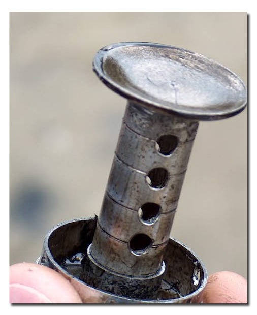 And this is how the internals look after the rebuild.
The picture is showing the first one I did, the later rebuilds (and this one later on) got a reinforcing aluminium-ring of 5mm thick so the M3 bolts have more 'meat' on the threads.
The first-stage 150% with the 130% second-stage is measured @ 82Db(a) .
With added SS kitchen scrub in the second-stage part it's measured @ 80Db(a) .
***************************************************************
NOTE FOR EDITOR ......... POSSIBLE : add here picture : muffler.jpg with this text :
About another way of making a muffler is written here before by *[person]* >>> link to MGB-article ******
OR (if this was NOT a MGB article and I copied the pic's from Int.Waters/RCboat/Jim's)
Another way of making a muffler is seen here , no idea anymore where I found it ,
with excuses to the maker of the original pictures.
****************************************************************
For the ones that want to keep their boating-waters ,
now you have a example how to cut back on the noiselevel.
Feel free to use these ideas , and I welcome real dyno-testings by the pro's.
Hendrick Spoor (aka HendricX)
(as the k and S together in my language is pronounced X)
Email link for HendricX = This email address is being protected from spambots. You need JavaScript enabled to view it.

