
Learn how to make a simple mandrel...the perfect DIY tool for machining and releiving the ring area of pistons on a lathe.
If you own a Zenoah G260PUM
engine, and chances are you do, you should know that if this engine is to be
modified, the first thing that should be done is to "relieve" the
piston in the ring area to prevent seizure. The fit of the piston in the
cylinder is ok if the engine is run stock and broken in slowly, but for
modified applications the fit is a bit too tight and seizing of the piston in
the cylinder will most likely happen unless this modification is done to the
piston.
Since I like to do a lot of my own engine modifications when I have the spare
time, I decided to make a simple mandrel that would make it easier to machine
the ring area of the piston on the lathe. To relieve the piston, you want to
remove about .002" from the diameter of the piston, from the top to
approximately .250" down. These are numbers that have worked for me. This
is easy to do on just about any size lathe, but having a suitable way of
holding the piston in the lathe is important.
Here is how I made my mandrel. It is very simple in design but serves its
purpose well.
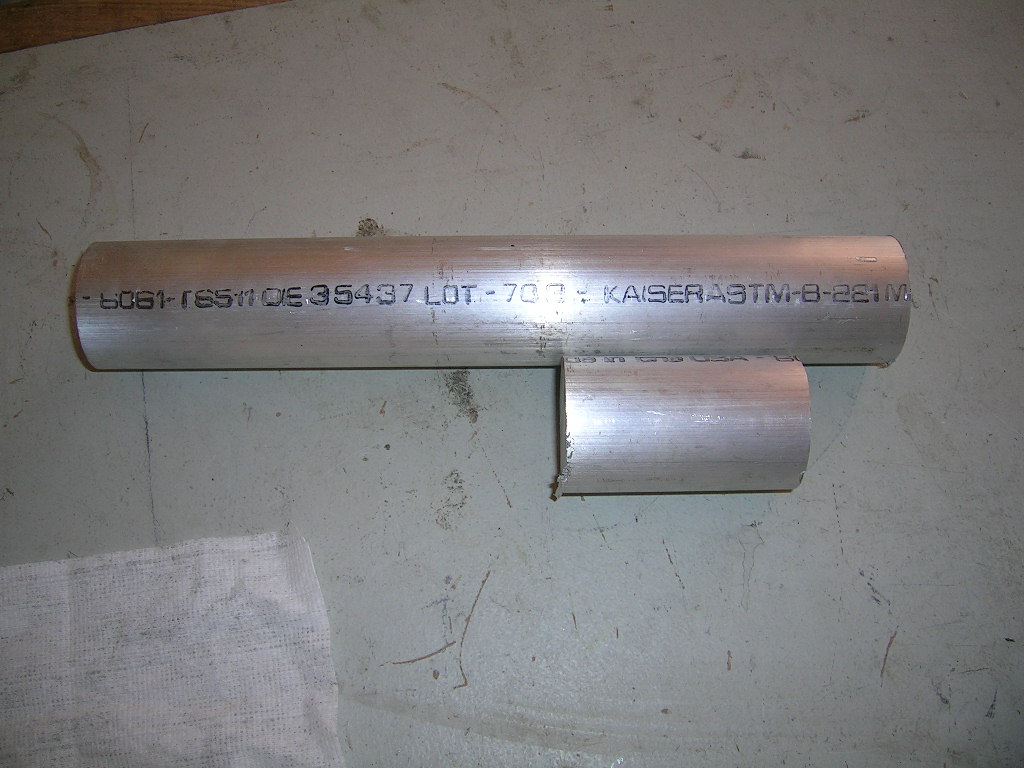
Here is a picture of the bar stock material I used to make the mandrel.
I cut it to approximate length as my lathe is small and this size rod will not
pass through the center of the chuck.
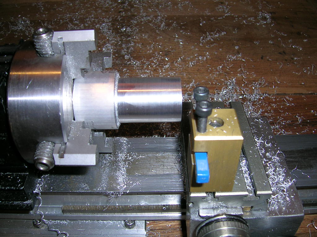
I started by machining one end of the piece to the diameter I wanted. This end
is the end that will be held in the chuck when I machine pistons. I kept it big
enough for sufficient rigidity. The last thing you want is a weak mandrel that
will bend or bounce. I also faced the end to get it nice and square. For added precision, I should have kept this end as short as possible. I might get to shortening it eventually!
I then flipped the piece around and held it in the chuck by the end I just
machined. At this point I machined the outer 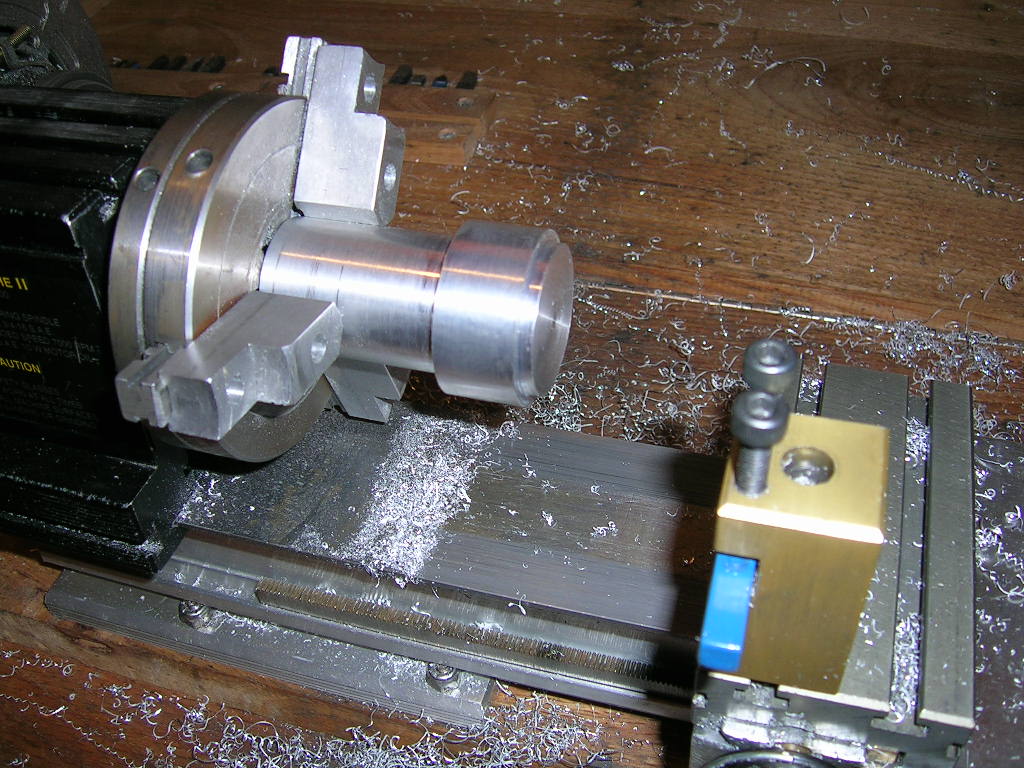 diameter of the piece
to get perfectly round. On the end I cut a groove that will accept the piston.
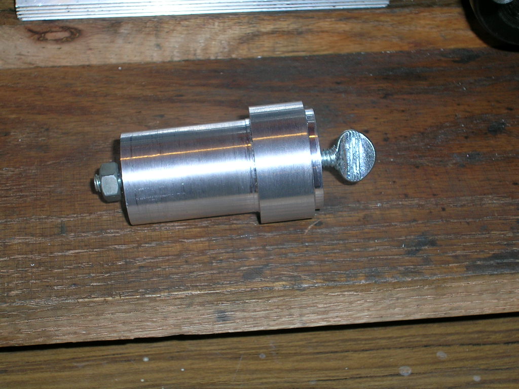
The groove is sized to allow the piston to sit snug on the mandrel. If you look
inside a piston you will see there is a step at the bottom of the skirts. This
is machined and precise for manufacturing purposes. I decided I would use this
step as the rest point of my mandrel. The I.D. of the piston at the bottom of
the skirts up to this lip is 32.00mm. I made my mandrel 31.96mm and it fits
just right inside the pistons. The groove in my mandrel is deep enough so that the
piston skirts will not bottom against the mandrel. It centers on the I.D. of
the piston and butts against the inside steps in the piston. This seems to work
really well for repeatability from one piston to another so far.
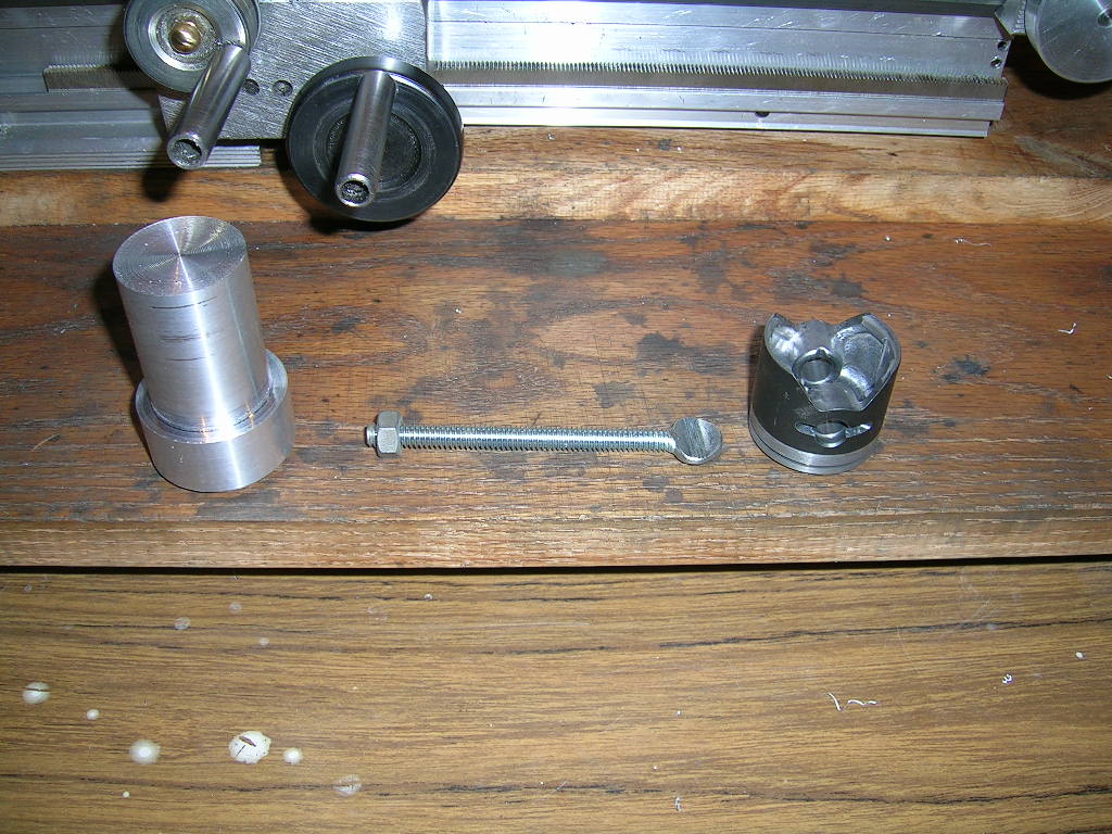
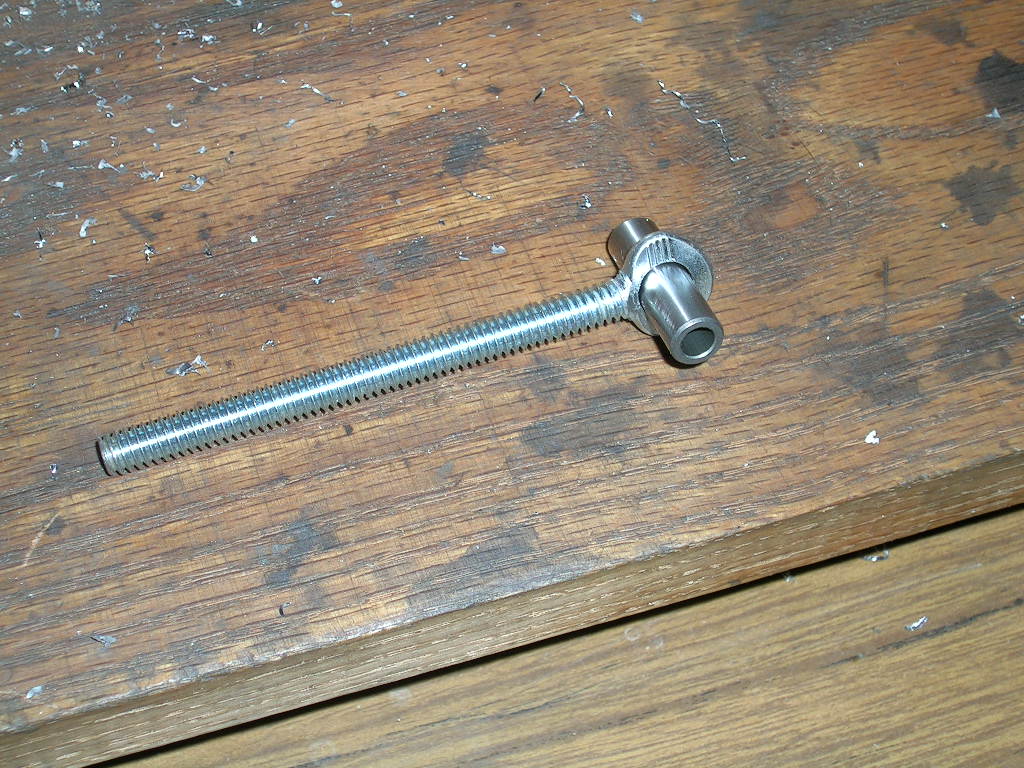
The next thing I needed was a draw bar to hold the piston to the mandrel. I got
a little bit lazy here and used a long 1/4" thumb bolt I had laying
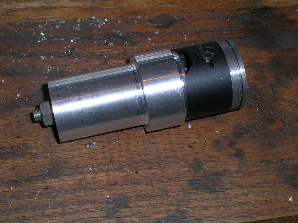
around. You can see it pictured here with the piston and the mandrel.
The draw bar must pass through the center of the mandrel, so I drilled a
1/4" hole all the way through.
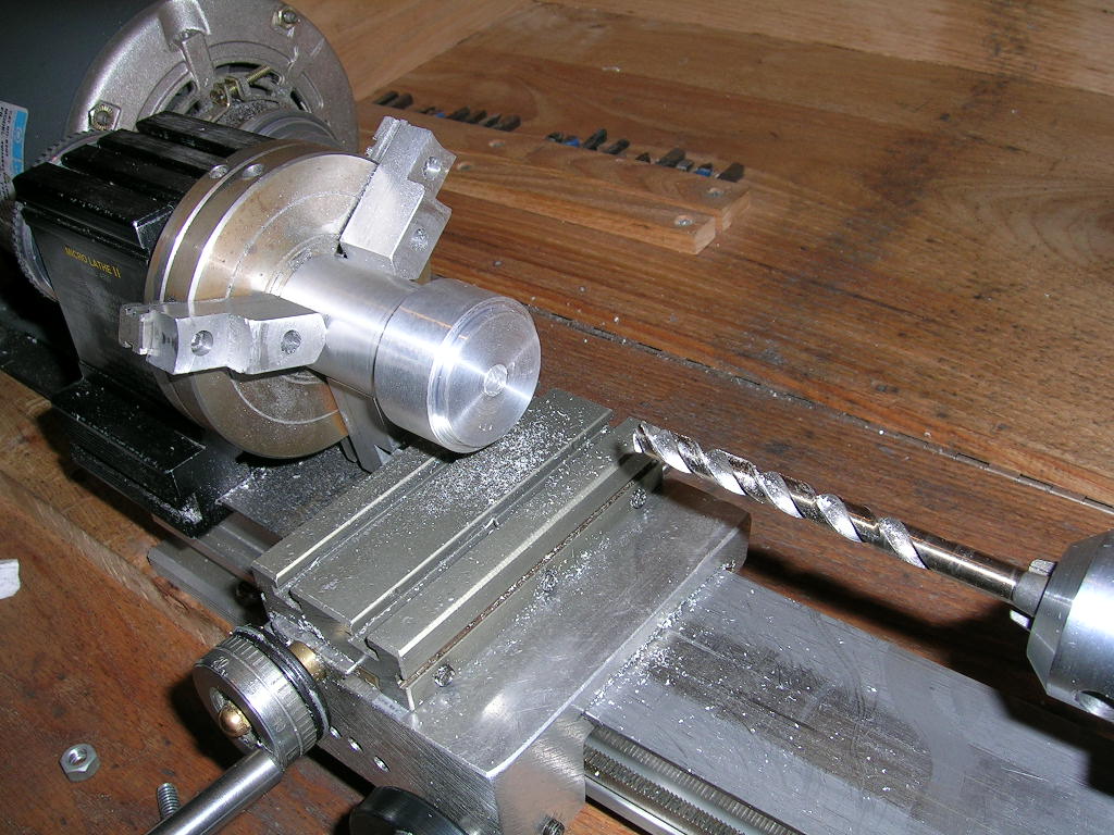
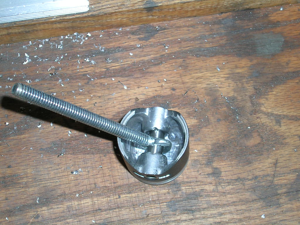
For the draw bar to work we need some way of it holding the piston. This was easily
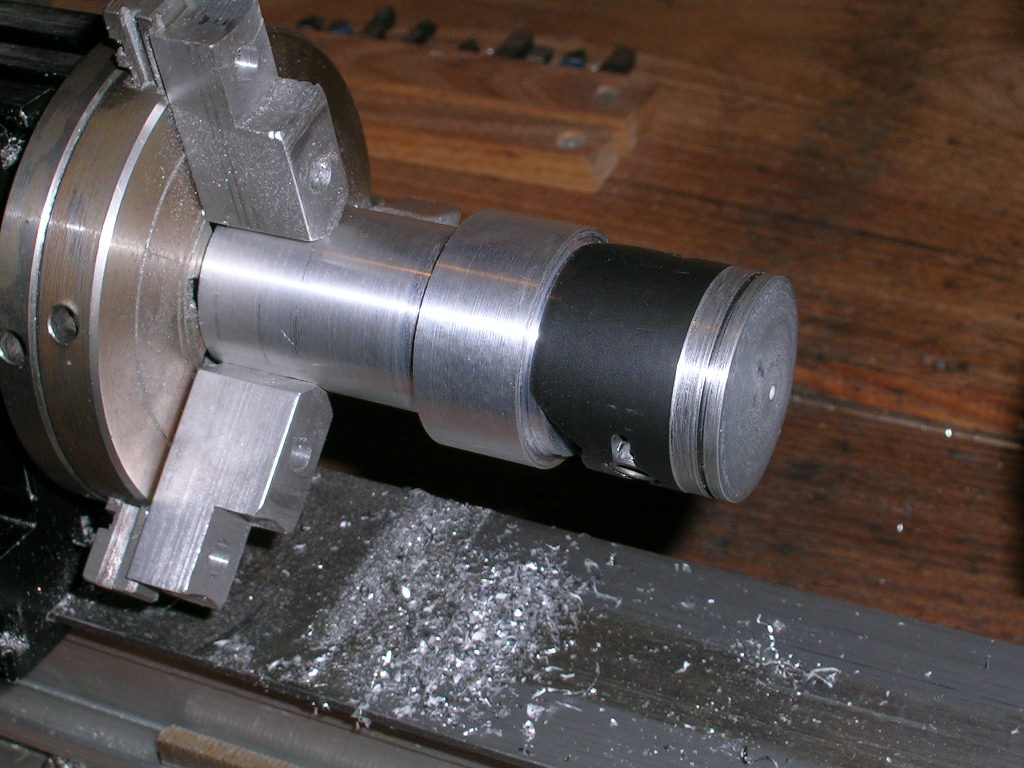
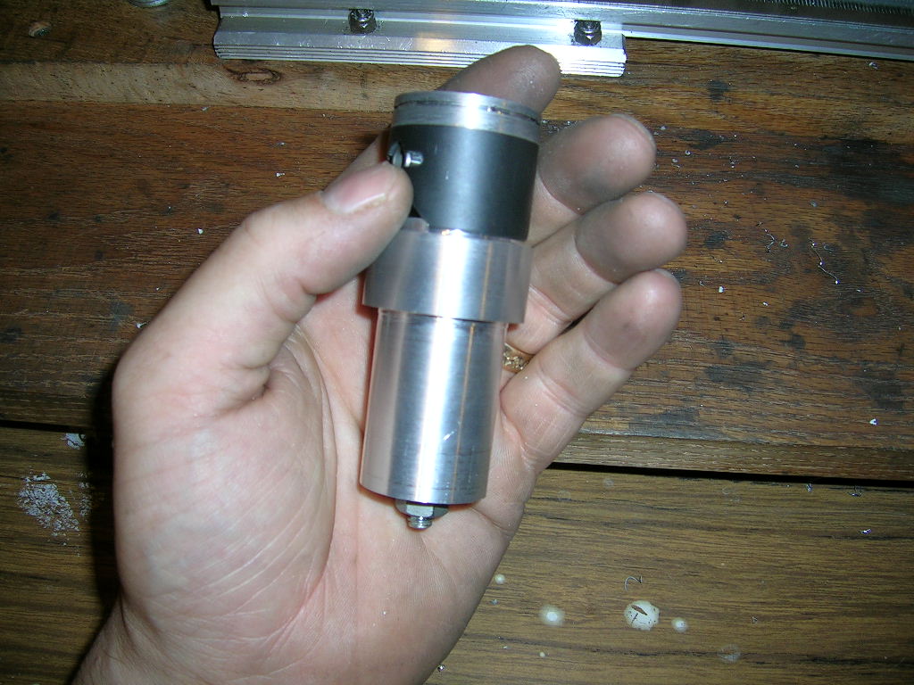
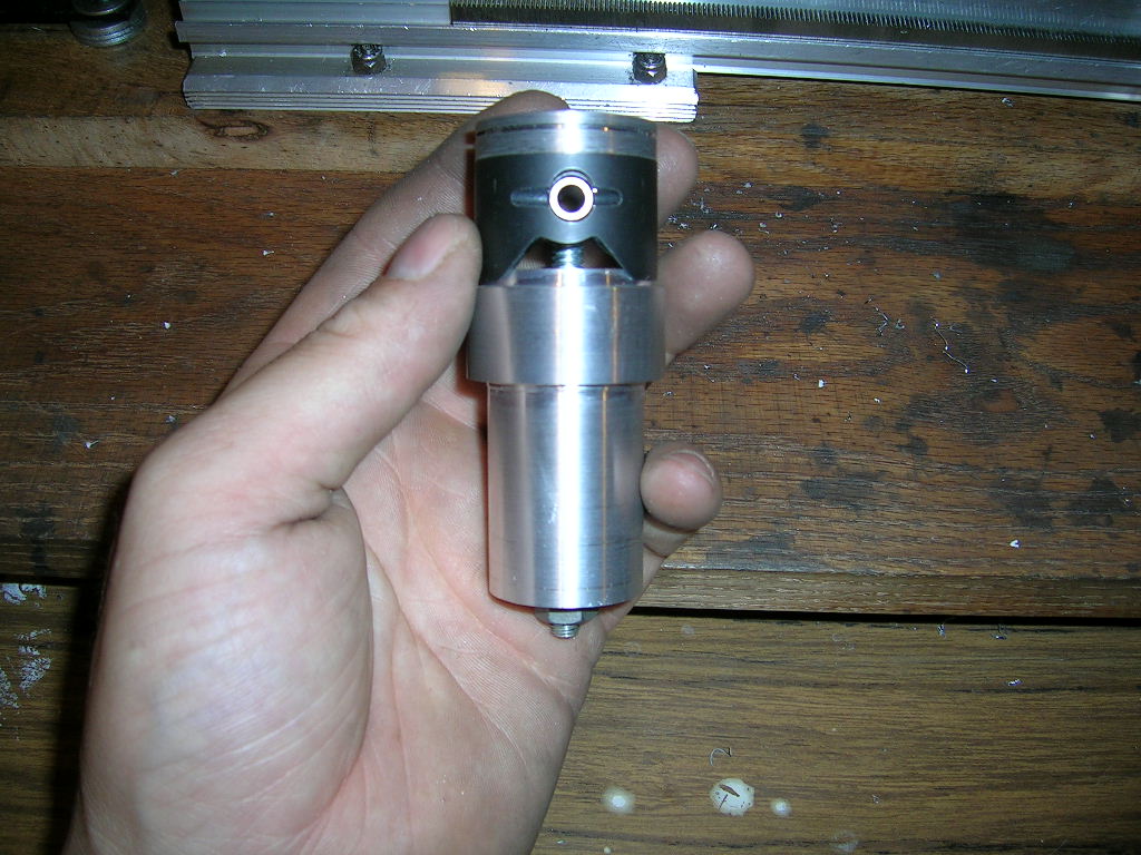
accomplished by drilling is to accept a piston rod. That's it. All done! Here
are a few more pictures to show how it all goes together and what it looks like
in operation.
Happy Machining!
Read Carlo Catalanotto's (CC Racing Engines) explanation why this modification to the piston is required on Zenoah G260PUM engines. LINK TO ARTICLE.

