Hobby Machinist Article...By Marc Weijenberg

Another informative article on hobby machining...this time learn how to make an adjustable strut...
Let me just give you an idea how I got interested in machining and using a lathe and forming metal. I have been a yachtbroker for many years mostly using my brain and my mouth to get along. I always enjoyed the mechanical side of our hobby and looking forward in manufacturing some hardware myself.
After browsing the internet for lots and lots (and I mean lots!) of useable information, I found myself overwhelmed in making a good and sensible choice in what to buy (lathe and milling machine).
My dear boating pal Andre Abtmeyer (you have seen him on Jims R/C Boat Dock also) was very helpful in making the right choices here. Andre has shown many of us through his fine articles here on Modelgasboats.com, the first steps in working metal into useable shapes and sizes.
After buying a small lathe and milling machine, there is still a lot of things to add before you can make anything usefull. Different chucks, clamps, collets, end mills, calipers, surface guage, centre drills, set of reamers, tool blanks, etc. The list is endless. This also means quite an investment from the user (yes you!) and eats a large portion of the hobby budget. Making hardware yourself does not compete with the prices currently on the market today, but oh the joy when you can say you made everything yourself! I cannot compare that money-wise. Not so much in showing off but you can actually create something out of bear metal. It is very satisfying to hold a piece of your "own-creation" in your hands. Now I am starting to ramble..... back to basics.
I already made a strut and a couple of t-bars for boating pals and finally I have built enough confidence to make something for my second MHZ roundnose hull I picked up this summer. I knew that a fellow German boater, Klaus Detro (aka germanboater) had posted some pictures and drawings of an adjustable strut-bracket on the internet. I forgot where, so through a short email, he pointed me in the right direction, toward Andre's website under the link "good ideas" (how appropriate).
I downloaded the pictures and drawings and printed them out. After studying them very well (it is better to read three times, measure twice and cut once), I put the measurements on a piece of 10mm thick aluminum. I used a waterproof marker to create a dye. After scribing the measurements and positions of the holes, I sat back and tried to figure out what steps (for clamping the workpiece) I should follow. This to ensure I would not get caught somewhere down the manufacturing process and not be able to clamp the workpiece for some of the later steps. I sometimes even write down the steps of machining/drilling the workpiece, just to remind me. I took some pictures along the way, not the best of quality though. I have to take some lessons from Andre.... again!
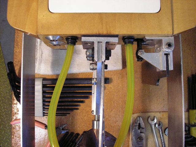
 The drive itself is comprised of four(4) major parts plus some allen screws. A mounting plate, a strut bracket with counter plate and two moveable arms. This setup allows for some sideways movement of the strut. Tilting the strut can be done by the "classic" loosening-the-screws method we all commonly use.
Mounting Plate
This piece that holds the strut bracket on a double pivot point, is simple to make. Just work carefully and it leaves enough possibillities to make some individual alterations. I made it the same as on the drawing. I did the holes, slots and drilling first and then the outline of the workpiece. To make the workpiece smaller, I used a simple table sized bandsaw. Not to stress the band-saw too much, I drilled many holes around the outline so the workpiece hangs only just along the "bridges" between the individual holes. Then I cut along the holes, cutting only the bridges. This works fast, safe and easy. After the work piece was almost ready, I used the fly cutter to clean it up. The use of the fly cutter has been described in earlier articles in the Machinist section.
Strut Bracket
This workpiece is a bit more difficult. It is not symetrical and I almost got into trouble not thinking through the clamping steps enough. I managed to clamp it, but the next time I will do it differently. The pictures show the individuel steps. After the milling is done, a trial fit is useful.
Moveable Arms
These are quite simple to make. I had some 5 mm thick aluminium in almost the correct size. I used a small saw blade on an arbor for cutting it to the correct size. Using some cutting fluid, the saw blade cuts the material cleanly and accurately. It also leaves a nice surface finish. I slotted the arms so it looks more scale.
There are a few threads to cut. I did this as one of the final stages. The workpiece can be ruined by making a pass too many or too deep in the earlier steps of fabrication. Threading is one step extra and I rather keep the taps nice and sharp by using them only when needed.
After making all the pieces I put it together and had a good look at it and was very pleased with myself. After polishing all the pieces it even looked better. Once set on the path of making your own hardware, you will start to make all hardware yourself. A rudder blade is in my opinion, the most difficult single part of them all. The angles are not too difficult, but drilling the waterfeed canal in the back of the rudderblade is something different.
So if you have a mill and a lathe already, do not be afraid to attempt this type of adjustable strut-bracket. It can even be made with just a drill, a set of files and a fair amount of "grit and elbow-grease".
Marc Weijenberg (aka devalkmp)


 .
.