Bernoulli Water Bailer

How-To Article ...by Patrik Tegelberg 

DSC00883_s.jpg


Learn how to make this automatic water bailer that works without any moving parts!


Here will describe a water bailer that can readily be made by everyone using easily available and inexpensive hardware. One only needs a short length of brass tubing and a short matching hose (silicone tubing). The end result is no more complicated than can be seen in picture 1 as the loop in the stern.


ImagePicture 1. The looped hose in the stern is a Bernoulli water bailer.

I call the water bailer a Bernoulli(1) water bailer because it utilizes a principle that is called the Bernoulli principle.(2)


V2 / 2 + g * h + p / r = constant


...states that as the velocity (v) increases, the pressure (p) decreases. So if we have access to high velocities, which we hopefully have, we can potentially have access to low pressures i.e. suction.


The loop in picture 1 leads from a pickup tube (placed where the water is expected to be) to a hole in the bottom of the hull outside which the water passes at high velocity and thus creating the suction needed to transport the water from the inside to the outside. The loop of the hose is such that its highest point is above the waterline when the boat is at rest in the water. This creates a barrier to stop the water from flowing back into the hull in case of a stop. If the water were to reach around the loop it would become a siphon and the boat would fill up with water. To prevent this from happening in case of a wave or other disturbance hitting the boat, there should be a sufficient margin from the highest point of the loop to the waterline; but keep in mind also that the higher the loop the more suction is needed to start the bailing.

When the boat comes to a stop the water rushes forward leaving the pickup dry to clear the hose of water to prevent the siphon to start immediately, or that is the theory and it has worked for me so far. When the boat is accelerating the water is rushing to the stern and is climbing up the transom to reduce the water column height needed to overcome to get bailing started, this works to our advantage and it is wise to place the pickup accordingly, that is far back close to the transom. I have used 5 mm inner diameter tube and hose. To get some real throughput the hose must not be too small.


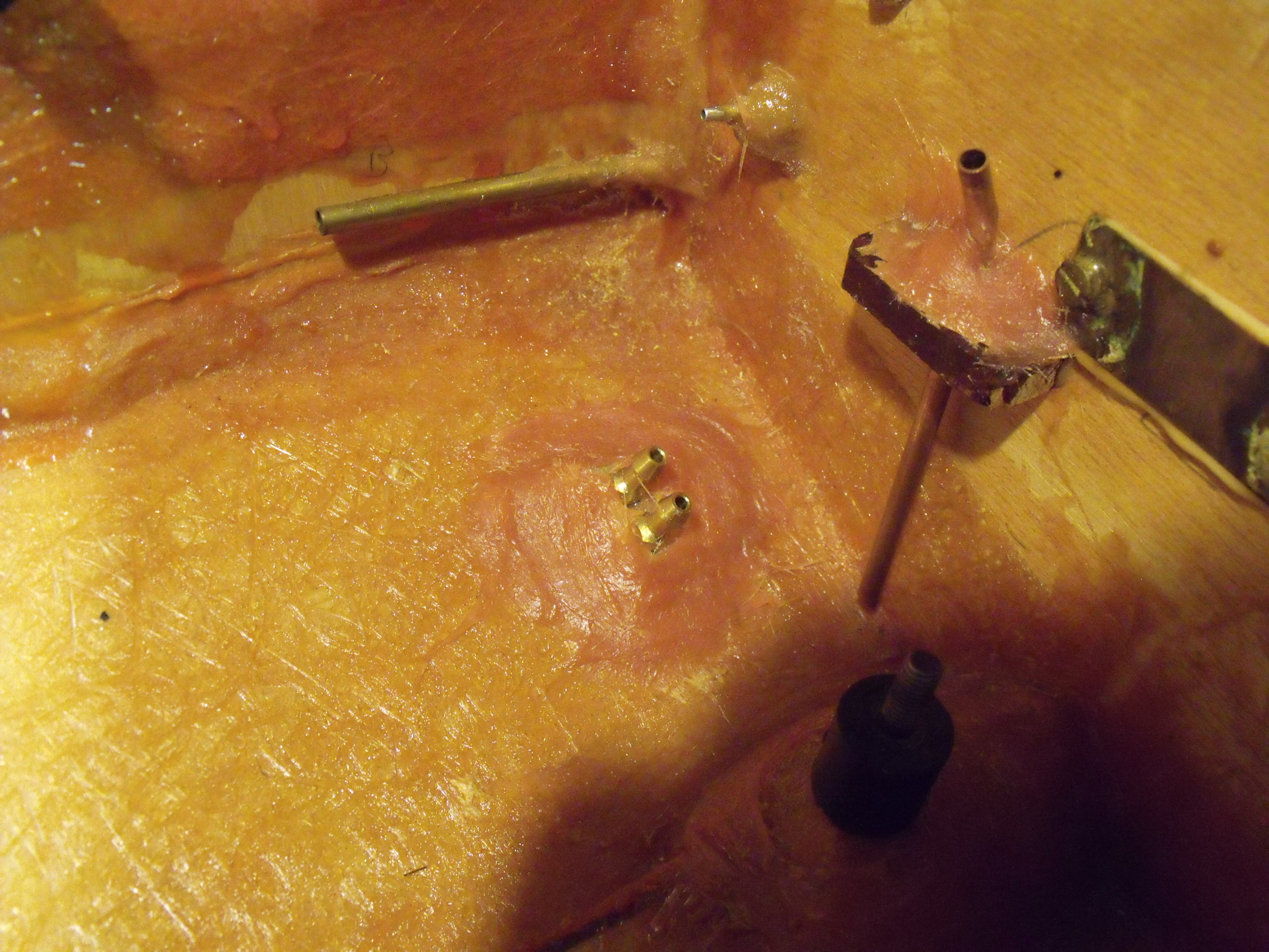
The trickiest part is to place and shape the hole in the bottom. It should be shaped kind of like a reversed water pickup with a small ramp in the front and a smooth aft edge. The thing that must not happen is that the water hit the aft wall and start pushing up into the boat. Also for this to work the hole must be surrounded by water so it must be some distance from the transom so that the water coming off the ramp has time to reconnect with the bottom of the hull before the transom. I put my hole about 4 cm (approx. 1.5 inches) forward of the transom as can be seen in pictures 2,3 and 4.


ImagePicture 2. Hole placement of drain.


ImagePicture 3. The brass tube is folded to yield a ramp, some tough putty would suffice to. The chip in the gel coat is not part of the construction.


ImagePicture 4. The smaller brass tube is just a dummy drain used in the pit.


The no moving parts character of this bailer renders it a very low maintenance unit. As a conclusion it can be said that I needed a bailer for my boat and this delivered a shipshape solution!


(1) http://en.wikipedia.org/wiki/Daniel_Bernoulli

(2) http://en.wikipedia.org/wiki/Bernoulli's_principle


Top

Log in to comment

whitefish replied the topic: #20217 11 years 6 months ago
I have read several descriptions of Bernoulli vacuum ports, i.e., the portion
which penetrates the bottom of the hull - not the part which suctions water
from the bilge. Which of the common configurations is the easiest to install
and also the most effective has always puzzled me.

To read the article about Bernoulli water bailers, please see:


www.modelgasboats.com/Bernoulli_Water_Bailer/


There are three drawings included with this post:

Drawing A: This is an image I borrowed from Craig D. (many thanks) and I'm
using it as a reference for boat position, direction of travel, water flow,
labels, etc. in the other two drawings. The tubing and water inlet (which I
did not draw) is assumed to be the same in drawing "B" and "C". Drawing "A"
displays a flush mount vacuum port and the attached hose barb and water tube
with a forward angle.

Some Bernoulli installations are using a bottom mounted water pickup which is
mounted in a reversed position. My understanding of this method is displayed
in drawing "B" and "C".

Drawing B: In one instance, the builder described having the pickups hose barb
in a perpendicular position and commented that this required the addition of
a small leading ramp so I added a couple dash marks to represent a small ramp
being added to the forward part of the pickup.

Drawing C: In this instance, a reverse mounted pickup is flush mounted and
there is a slight rearward angle to the pickup's hose barb and vacuum tube.

Bernoulli vacuum ports are not easy to make clear profile pics of once
installed. Based on the searching I have done, the number of verbal
descriptions of different vacuum port installations far outweighs the drawings
and pics available, so I am trying to rely on simple line drawings to gain a
better understanding.

What I am hoping for is some of the experienced Bernoulli installers will
comment about how their method(s) compares with the different drawings. None
of these drawings show a configuration that I am suggesting is better or worse
- they only represent different ways Bernoulli vacuum ports could be
positioned and configured. It is also possible that I have not clearly
understood statements I have read so the drawings may not represent what a
particular builder was referring to.

Since the original article is over 5 years old it is also possible that other
novel ideas for Bernoulli vacuum ports have been designed so I'm hoping to
read about and maybe see some better mousetraps.
Craig Dickson replied the topic: #17109 12 years 8 months ago
Hi Woodie

The true test for me was trying this out in a relatively very slow boat. As per this youtube clip.(After others on the water subsequently sprayed prop wash into my hull I figured that the system worked quite well):

It worked for me.


Cheers
Craig
Woodie's Avatar
Woodie replied the topic: #17108 12 years 8 months ago
Hi Craig.

Well done. Just as I intend to do with my mono.
Nice to hear that this works good.
I will use two double water inlets. One for the engine (40 cc Blata) and one for cooling flange and exhaust.
In addition to that I will mount two reversed water inlets to work as water outlets (bailers). One on each side of the keel, as the boat is wooden build on a huge keel.
So I'm in for four double in- and outlets all together. And a nest of tubes, as you can guess. :laugh:

Cheers! :cheer:
Woodie.
Craig Dickson replied the topic: #17107 12 years 8 months ago
Hi Folks

Having test finished a 48” wooden scale Huntsman boat (that I started building many years ago) I decided to try out the Bernoulli auto bailer (good safe opportunity to try it out). The windows on the top of this boat were left open so when run with other surface drives plenty of spray went through them. When my boat came back home it was surprisingly dry inside so the method definitely seems to work.

And it is nice to know that the system requires zero maintenance and when the boat is stopped on the water there is zero leakage of water back into the hull.

Okay first image shows the boat on the water.


Second image shows the reverse mounted dual pick up viewed from the hull bottom.


Third image shows the inside minus the connecting tubes (prior to finishing with a good clean up of the fibreglass paste used).


Two silicon tubes lead into one looping over for the vertical pick up pipe. That gives sufficient vacuum suction to pull any water up the single vertical brass pick up tube to allow for siphon action to help drain any excess water out of the hull when on the move.

Cheers
Craig
Craig Dickson replied the topic: #15495 13 years 1 month ago
Hi Woodie

I see no problems as you will be utilising the same principle as in the original article. In time to come please do let us let us have an update once tested.

One aspect of this system that I am not sure about is the ideal diameter of the tubing to maximise water flow. If too large, the vacuum won't exert sufficient force to suck the column of water out. If too small, the water flow rate might be insufficient to deliver effective bailing.

I guess that experimention will answer that issue.

Regards
Craig

User Login

Mailbox

You are not logged in.

© 2017 Modelgasboats.com. All Rights Reserved.