Hobby Machinist Article ...
Learn to make a dial indicator holder that fits in the spark plug hole of your engine to accurately check squish band...
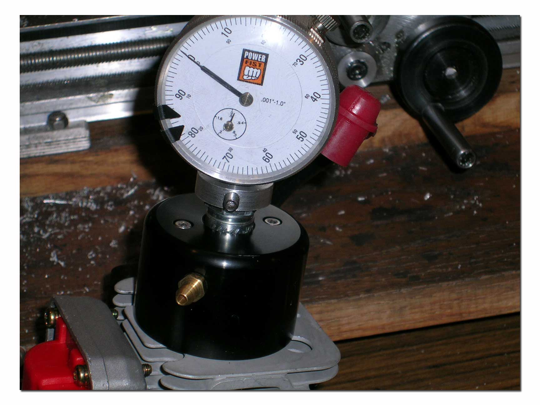
One of the most important things to be able to accurately verify on engines is the squish clearance. What is this you ask? The squish clearance is the amount of free space between an engine's piston and squish band when the piston is a top dead center (TDC). If your engine had zero squish clearance that would mean that at TDC the piston would touch the squish band in the cylinder head. Zenoah engines most commonly used in our applications have a one piece cylinder/head unit. Changing the squish clearance can be done using different thickness cylinder gaskets and/or by removing material from the base of the cylinder on a lathe. The tool we are making can be used to verify the results of such modifications.
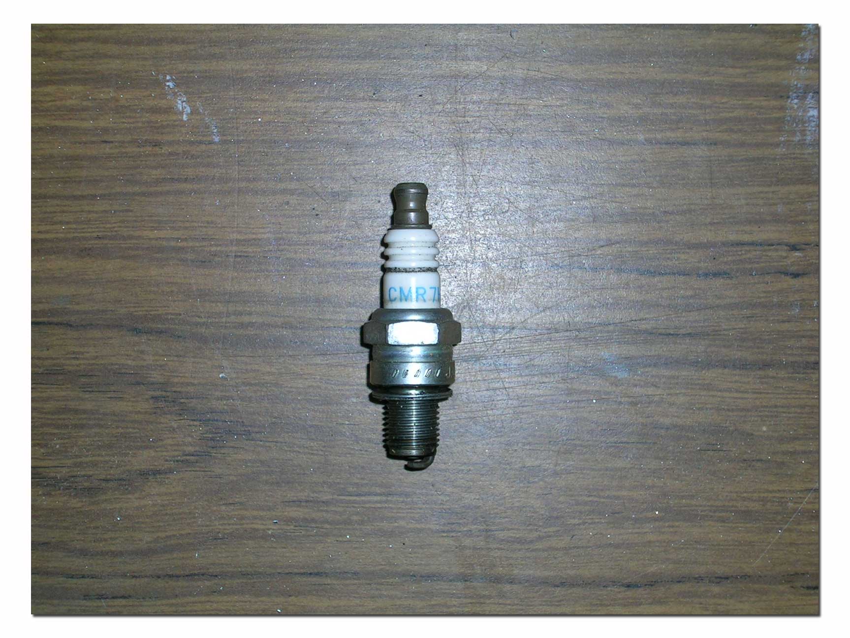 To make
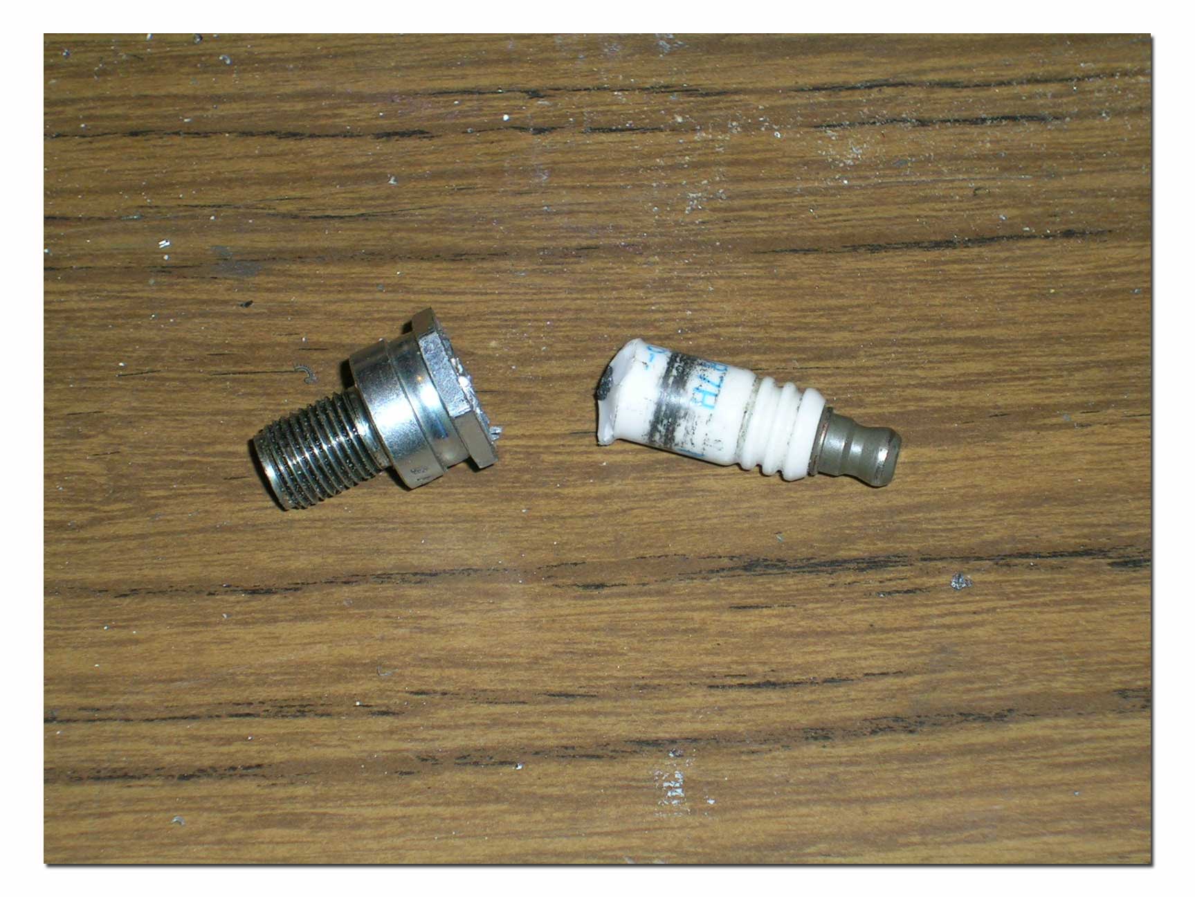
the dial holder, we start with an old (or new) sparkplug that fits on our
engines.
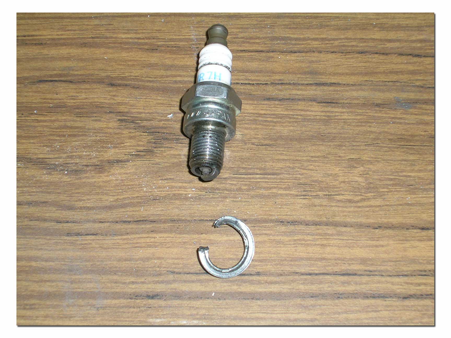 Pictured here is an NGK CMR7H, commonly used with the new generation Zenoah
engines, such as the G231PUM and G260PUM.
I start by removing the gasket from the sparkplug. This is easily done with a pair of cutting pliers.
Next, I setup the sparkplug in the lathe, gripping it just behind the hexagonal section. The goal here is to remove the metal lip that holds the insulator just above the hex. With this lip removed completely, the insulator will be easy to push out. Next I flip the sparkplug around and holding it by the hex, I remove the spark tip. With this done, it is now time to put the plug in the vise and push the insulator out. Setup the sparkplug electrode end up in the vise and use a punch and hammer to push out the insulator from the base. This should be fairly easy if you have machined all of the lip holding the insulator in place.
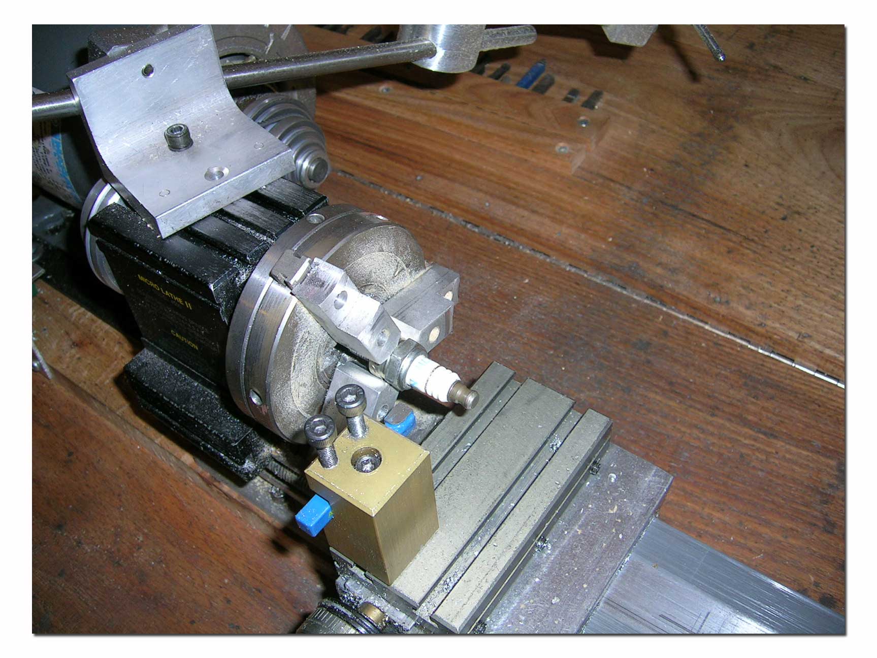
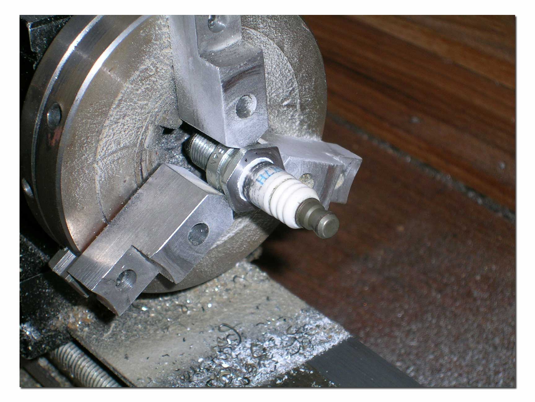
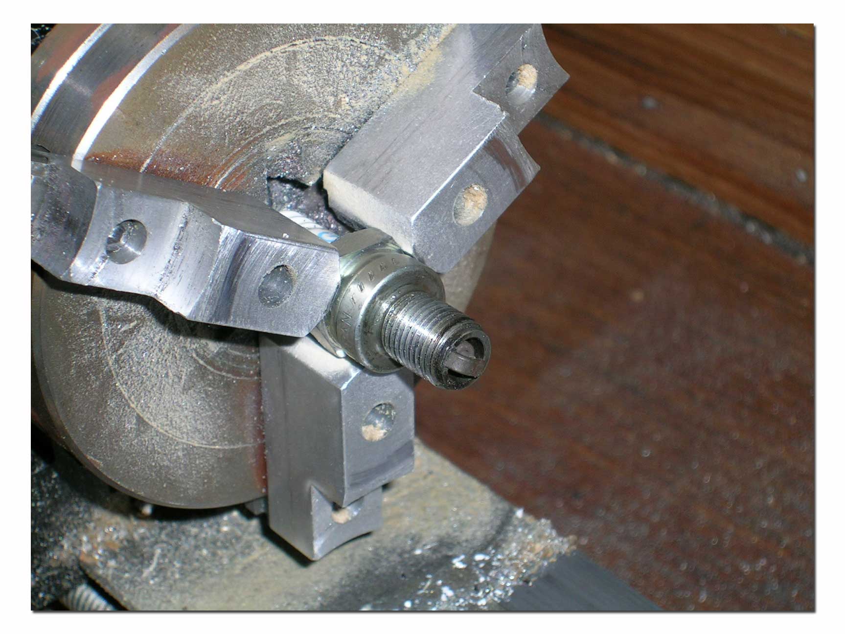
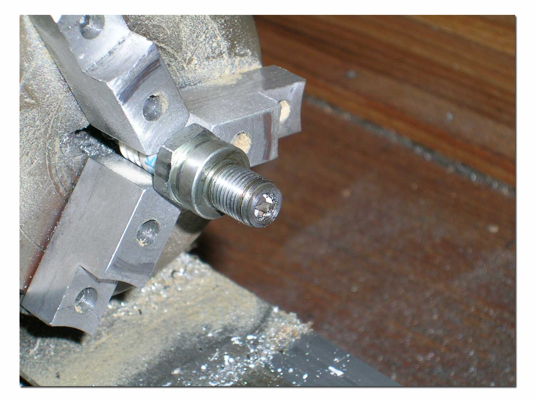
With the insulator removed, I return the sparkplug base to the lathe and drill the inside large enough to accept the shaft of my dial indicator. I also bored out the section above the thread to accommodate the part I will make to hold the dial indicator. I want this bore to be accurate as I will later press in the insert.
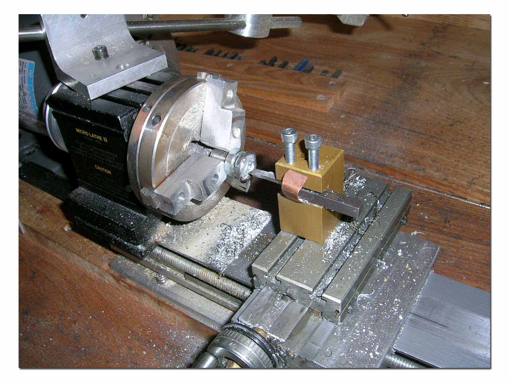
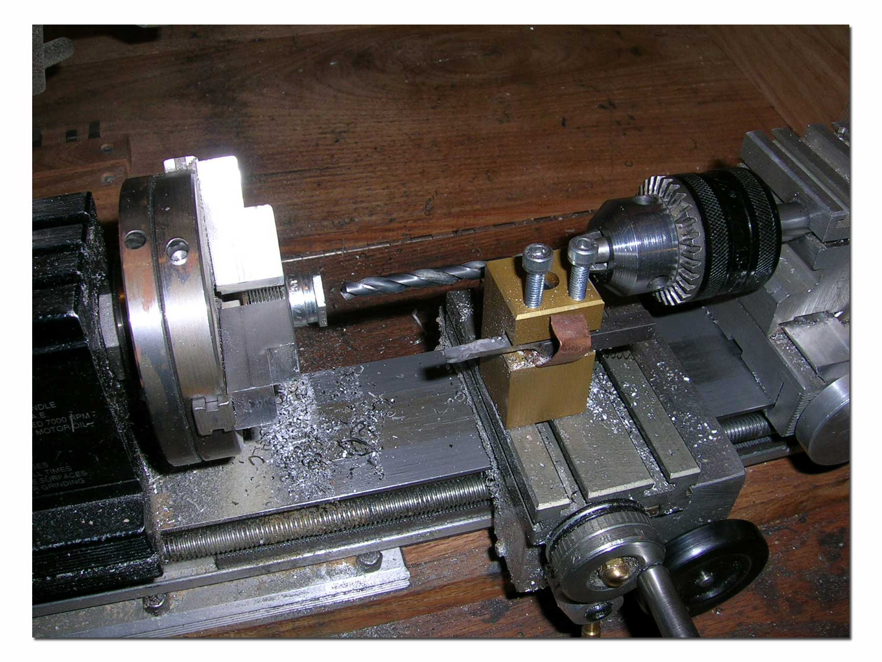
I made the dial holder insert with a piece of round aluminum rod. The first thing I did was machine the end that would fit inside the sparkplug base. This section is machined for a size-size fit. That is why I bored the inside of the sparkplug base...to get a good tight fit.
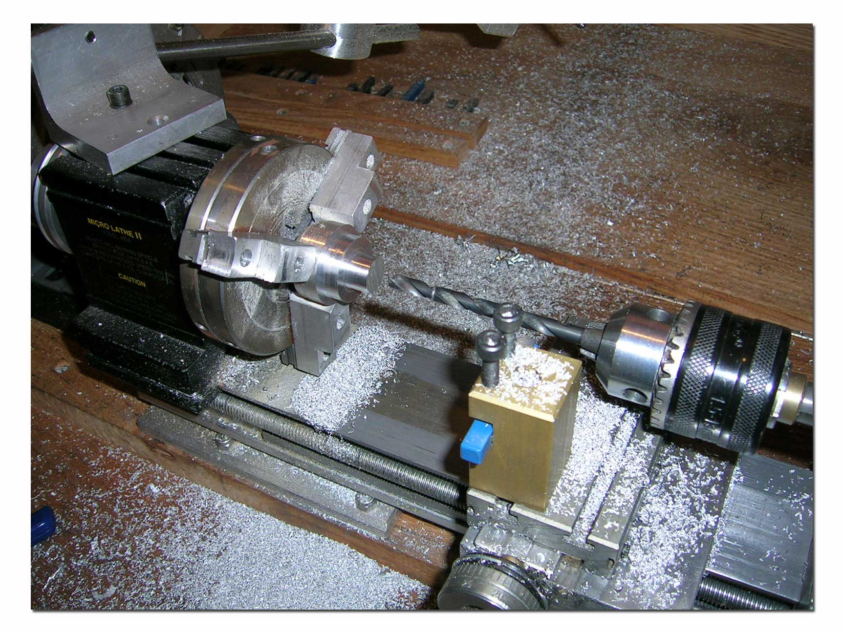
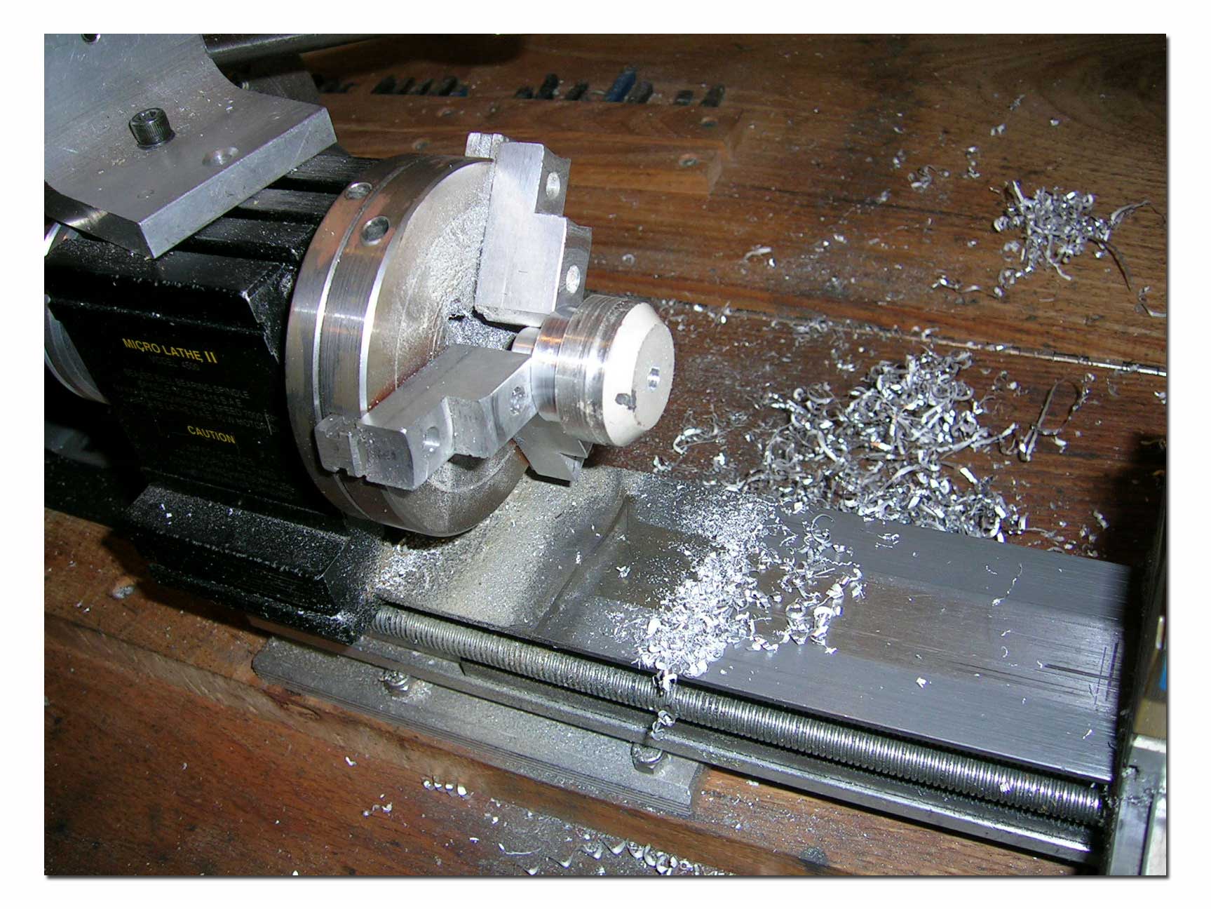
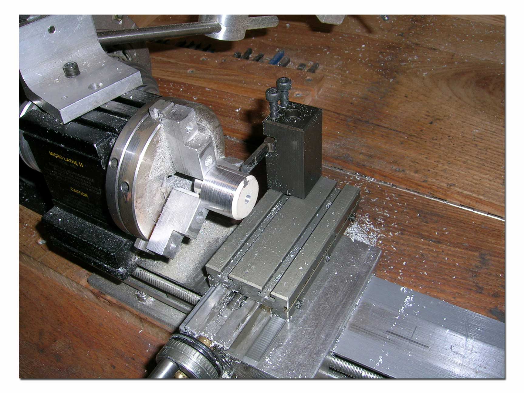
I then drilled thru the center of the insert to have a starter hole for boring. After turning the part around in the lathe, I bored the center of the insert for a snug fit of the dial indicator. I then finished turning the outside diameter of the insert and cut off the excess.
Once the insert is complete, I used the vise to press it into the sparkplug base. If the fit is correct, this will never move under normal use.
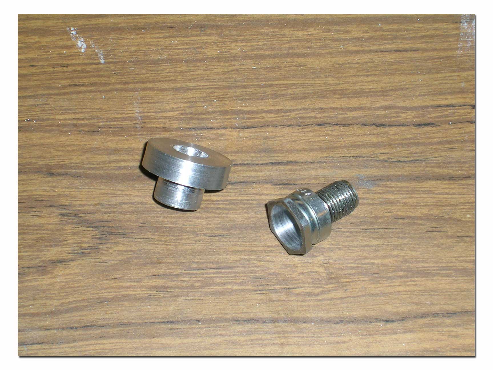
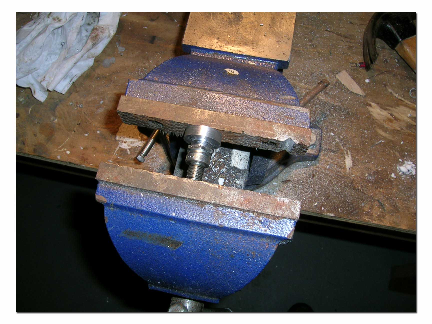
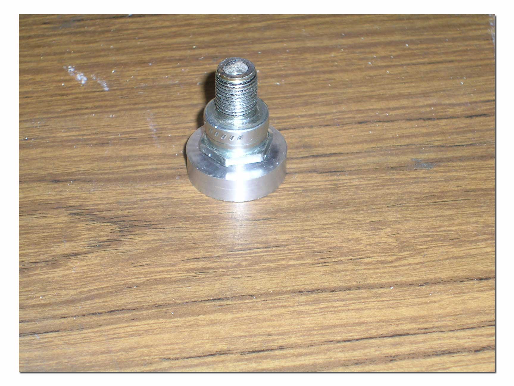
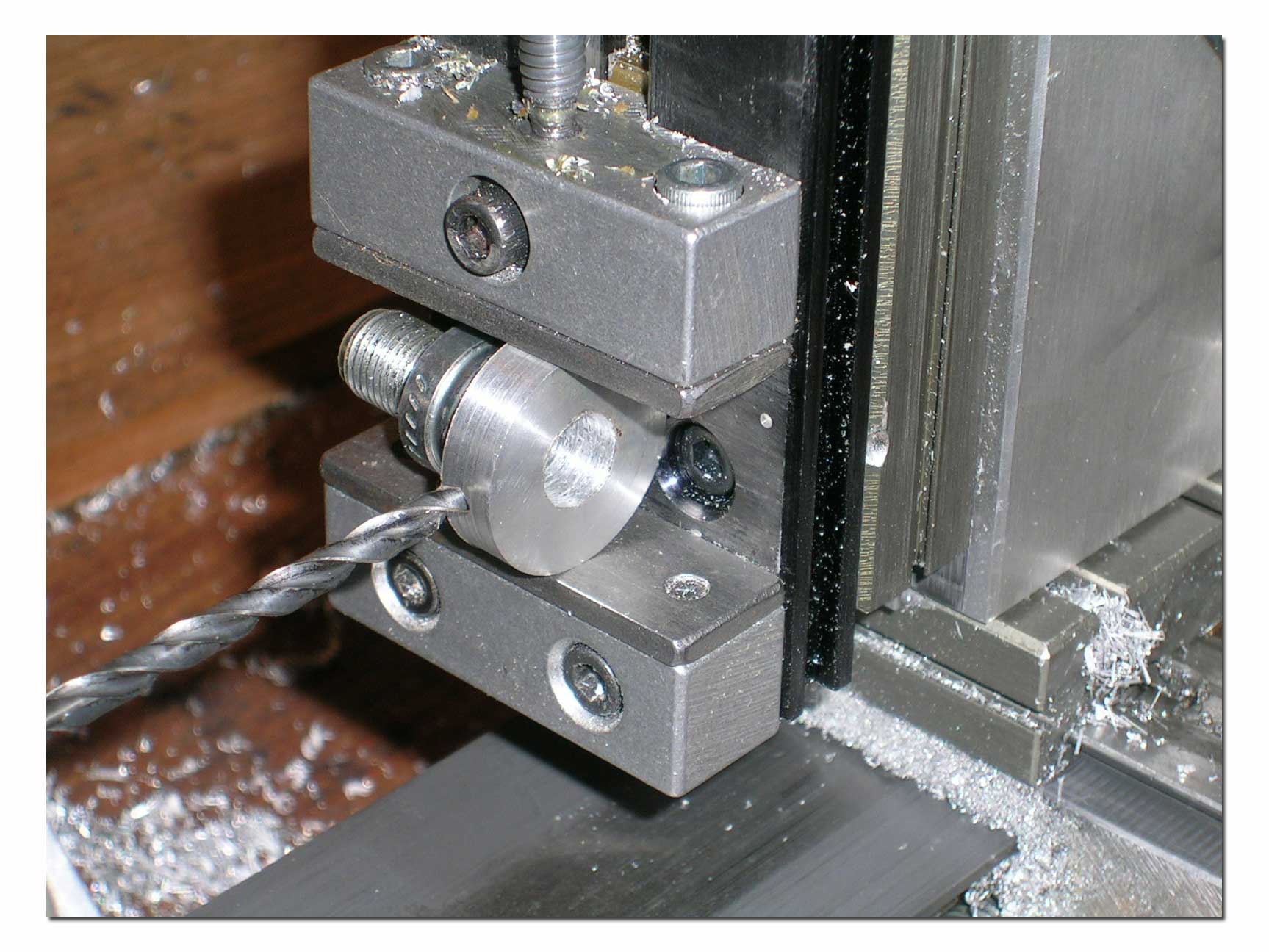
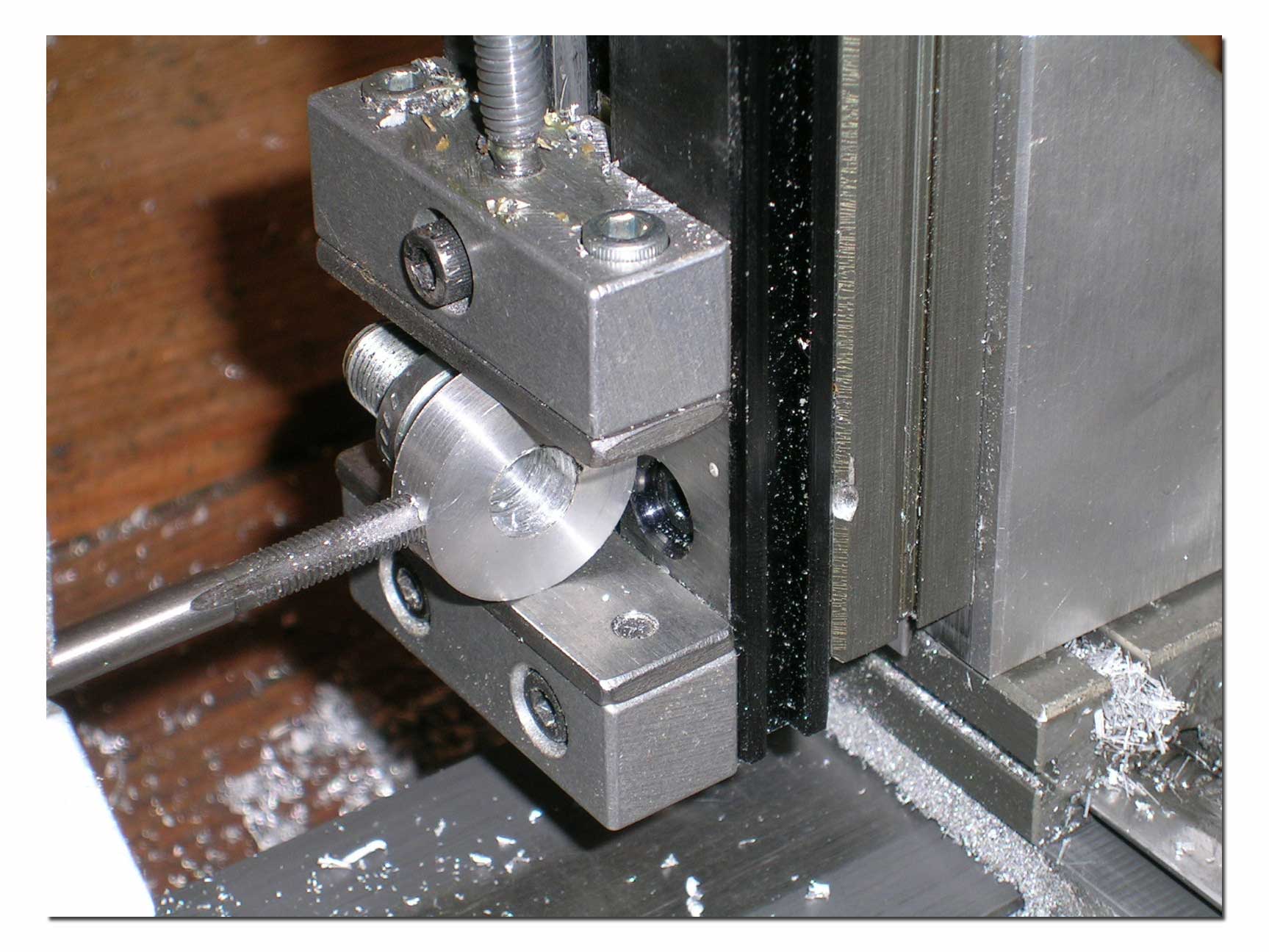
The last step is drilling and tapping the insert for a setscrew to secure the dial indicator in the tool.
The finished product...
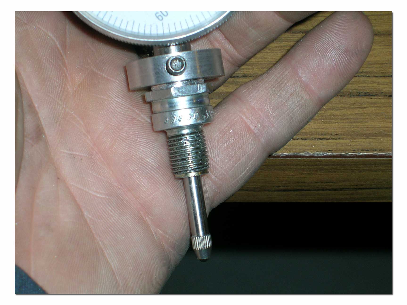
How to use this tool...
The most accurate method to measure squish clearance with this tool is as follows:
- Remove the cylinder from your engine.
- Remove one of the wristpin retaining rings from the piston and remove piston from connecting rod (be careful not to damage the roller bearing and spacers on the piston's wristpin, they will drop out when you remove the wristpin)
- Assuming the dial indicator is now mounted in the holder, screw the tool into the cylinder's sparkplug hole. Tighten it so it does not move.
- Take your piston and orient it correctly (arrow on piston crown pointed toward exhaust port) and insert it into the cylinder. Push it all the way up into the cylinder and hold it there while you set your dial indicator to read zero. (you can remove the ring from the piston for this step...it will make it easier to insert and remove the piston from the cylinder)
- Now pull the piston from the cylinder and re-install it onto the connecting rod with the wristpin, bearing and spacers removed (remember to use new retaining rings on the wristpin when doing the final assembly).
- Leave the dial indicator mounted to the cylinder...make sure is does not move.
- Re-install the cylinder on then engine and tighten all mounting bolts.
- Turn the crank slowly to bring the piston up to TDC (this will be the highest reading you get on the dial indicator). It should be somewhere close but below the zero you set in the previous steps.
- The difference between this reading and zero is your actual squish clearance on the particular engine being checked.
If you are doing modifications to the engine, you might have to remove the dial from the engine to perform some operations. If this happens, you will have to reset the dial to zero using the piston again. Simply re-installing the dial to the cylinder and checking squish will not yield the most accurate results.
If the crown of the piston in the engine your are checking is unmodified, you can save a lot of time by using a separate stock piston to set the dial to zero rather than removing the piston from your engine. There could be slight differences even in new stock pistons however, so if you really want the most accurate results possible, pulling the piston from your engine and using IT to set the dial to zero is the best method.
So there you have it... an indispensable tool, quick and easy to make!
Happy Boating!

